Sequential stepped directional control valve

a directional control valve and step technology, applied in the direction of valve housing, valve operating means/releasing devices, transportation and packaging, etc., can solve the problems of high disadvantage, dangerous, or even deadly, and the transition through a neutral position, so as to reduce the size or weight of the valve

Inactive Publication Date: 2009-03-05
PARKER HANNIFIN CORP
View PDF29 Cites 29 Cited by
  • Summary
  • Abstract
  • Description
  • Claims
  • Application Information

AI Technical Summary

Benefits of technology

[0013]A still further object of the present embodiments of the invention described herein is to achieve the above objects in a manner that is cost-efficient.
[0014]Yet anothe...

Problems solved by technology

Depending on the nature of the hydraulic application, such a transition through a neutral pos...

Method used


Image

  • Sequential stepped directional control valve
  • Sequential stepped directional control valve
  • Sequential stepped directional control valve

Examples


Embodiment Construction

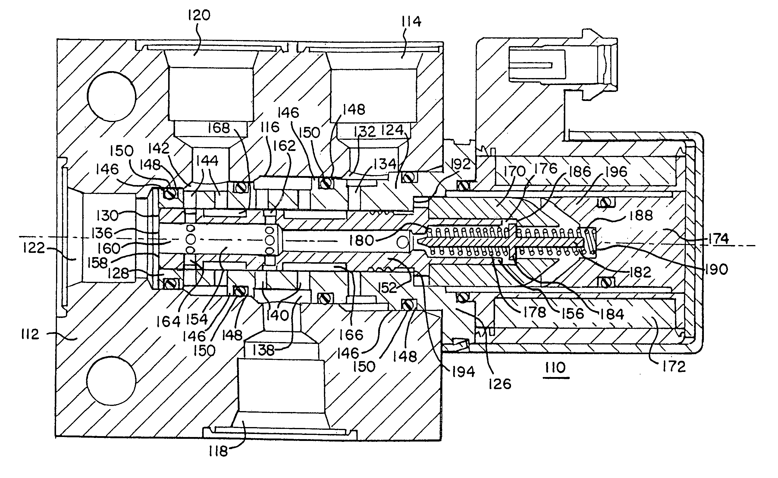
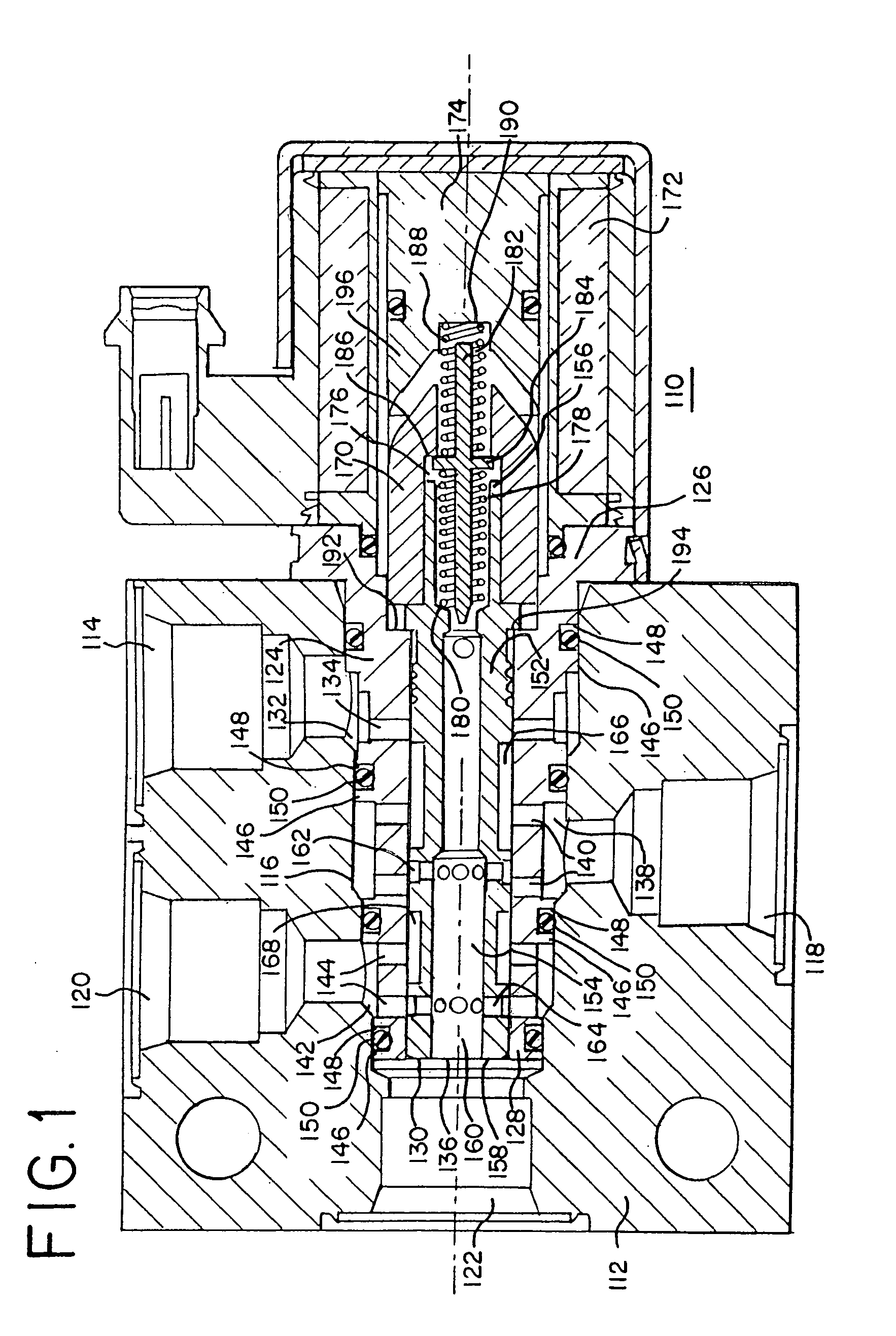
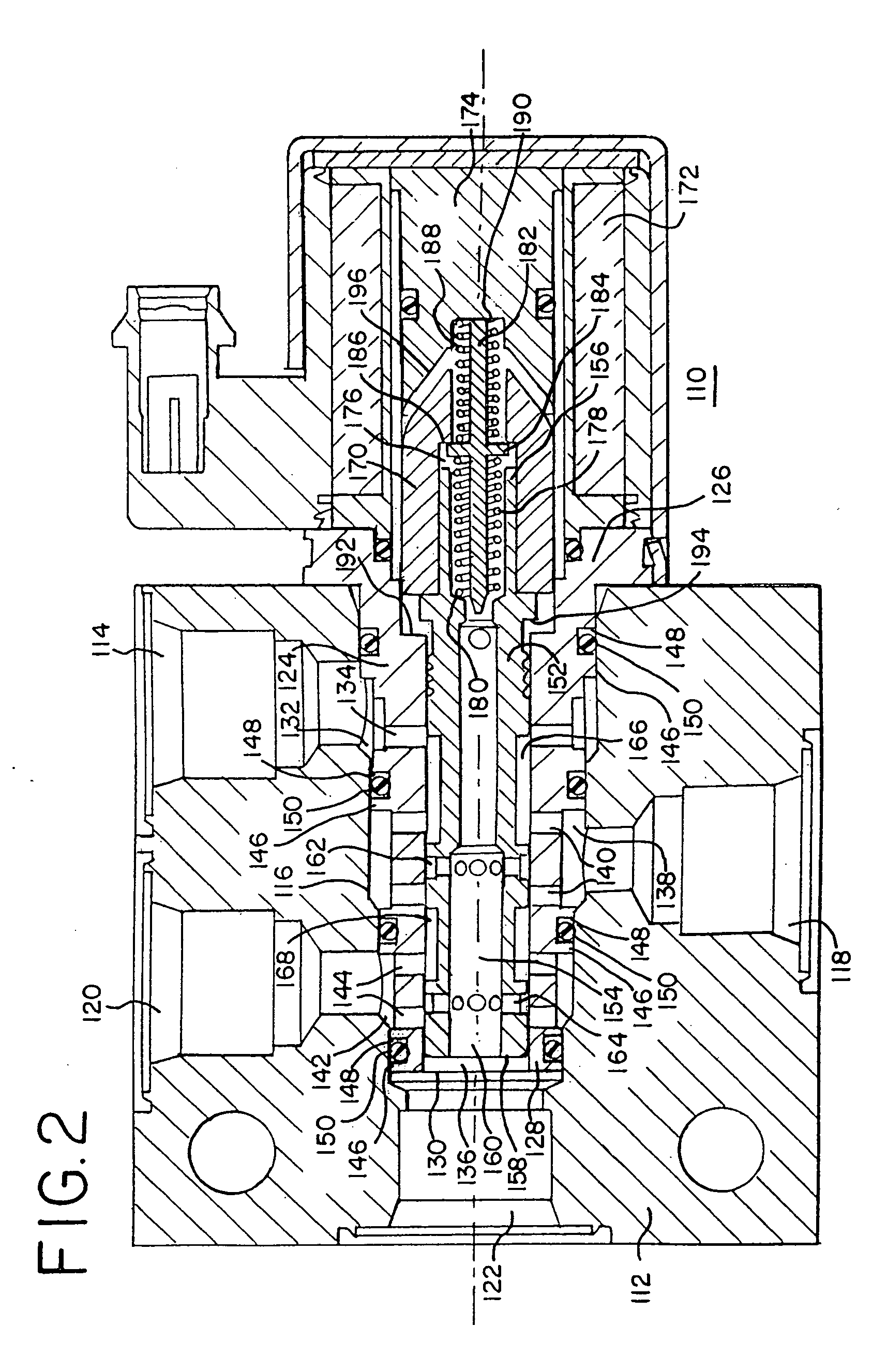
[0024]An embodiment of the sequential stepped directional control valve 110 of the present invention is illustrated in FIGS. 1-3 in a manner that would be understood by persons skilled in the art. For purposes of this description, the sequential stepped directional control valve 110 shall have a distal end or direction oriented in the direction of the tank port 122 and a proximal end or direction oriented in the direction of the portion of the sequential stepped directional control valve 110 opposite from the tank port 120. The lengthwise direction of the sequential stepped directional control valve 110 illustrated by the broken center line in FIGS. 1-3 shall be referred to generally as the axial direction, while the radial direction of the sequential stepped directional control valve 110 is transverse to the axial direction.

[0025]A body 112 in which the sequential stepped directional control valve 110 is utilized is illustrated in FIGS. 1-3. The body 112 may be found in any number ...


PUM


Abstract

A sequential stepped directional control valve accepts pressurized hydraulic fluid from a pressure port, and directs that pressurized fluid to a first stage port, or to both a first stage port and a second stage port. In the neutral position, the valve blocks the flow of pressurized hydraulic fluid into the valve. In the first stage position, pressurized hydraulic fluid flows into the valve and is directed by the valve to the first stage port, however, the fluid flow to the second stage port is blocked. In the second stage position, pressurized hydraulic fluid flows into the valve and is directed to both the first and second stage ports. When the valve transitions from the first stage position to the second stage position, the valve does not cycle through a neutral position, and the flow of pressurized hydraulic fluid to the first stage port is uninterrupted.

Description

CROSS-REFERENCE TO RELATED APPLICATIONS[0001]This application claims priority from and is related to the following application, Sequential Stepped Directional Control Valve, U.S. Provisional Application No. 60 / 968,114, filed Aug. 27, 2007. The prior application, including the entire written description and drawing figures, is hereby incorporated by reference into the present application.BACKGROUND OF THE INVENTION[0002]1. Field of the Invention[0003]The present invention relates generally to three position hydraulic valves used in a wide variety of hydraulic applications. Hydraulic valves of this sort may be utilized, for example, to cause piston movement and thereby cause operation of hydraulic equipment. One example of such an application would be engine brakes. The present invention relates to an improved design for such hydraulic valves.[0004]2. Brief Description of the Related Art[0005]Prior art or traditional three position valves utilized two solenoid coils, with one solenoid...

Claims


Application Information

Patent Timeline
IPC IPC(8): F16K31/02
CPCF16K3/26F16K27/048F16K31/0613F16K27/041Y10T137/86622Y10T137/86694Y10T137/86702
Inventor REILLY, JOSEPH PATRICK
Owner PARKER HANNIFIN CORP
Why Eureka
Try Eureka