Driving apparatus, exposure apparatus, and device manufacturing method

a technology of exposure apparatus and exposure coil, which is applied in the direction of electrical apparatus, dynamo-electric machines, cooling/ventilation arrangements, etc., can solve the problems of affecting the positioning accuracy of a stage, affecting and increasing the power consumption of the stator coil, so as to reduce the time and effort required to adjust the position and enhance the reproducibility of the position of the coil

Inactive Publication Date: 2009-03-05
CANON KK
View PDF5 Cites 23 Cited by
  • Summary
  • Abstract
  • Description
  • Claims
  • Application Information

AI Technical Summary

Benefits of technology

[0016]The present invention is directed to a driving apparatus that is capable of reducing the time and effort required to adjust the position of a coil each time the coil is cooled, and that is capable of enhancing the reproducibility of the position of the coil when the coil is cooled again.

Problems solved by technology

However, when electric current to be applied to the stator coil is increased, the power consumption of the stator coil considerably increases as Joule heating of the coil.
Thus, the positioning accuracy of a stage maybe adversely affected.
However, because the adjustment of the position of the coil is performed each time when the coil is cooled, it is difficult to restore the position of the coil to the same position each time when the coil is cooled.

Method used


Image

  • Driving apparatus, exposure apparatus, and device manufacturing method
  • Driving apparatus, exposure apparatus, and device manufacturing method
  • Driving apparatus, exposure apparatus, and device manufacturing method

Examples


first exemplary embodiment

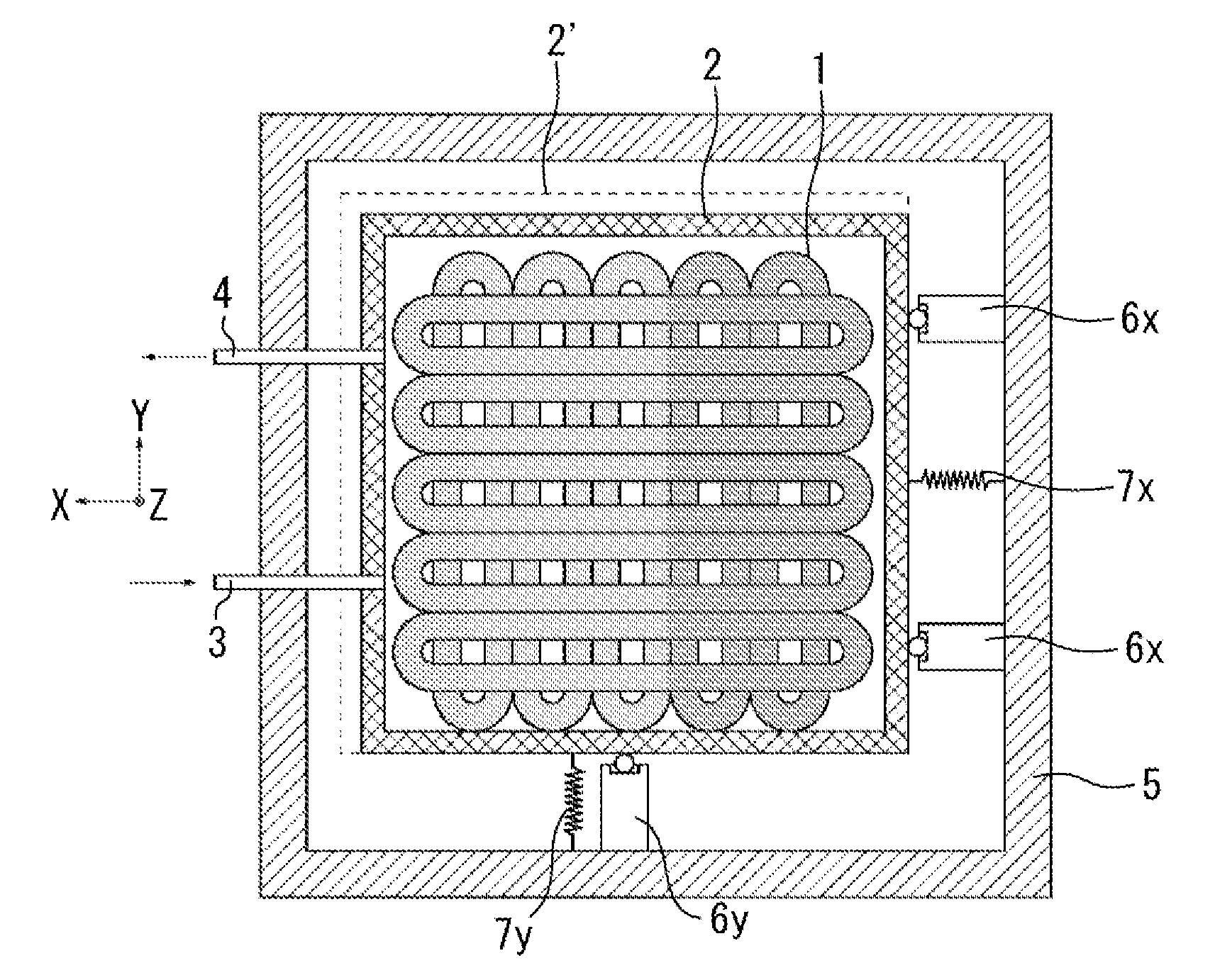
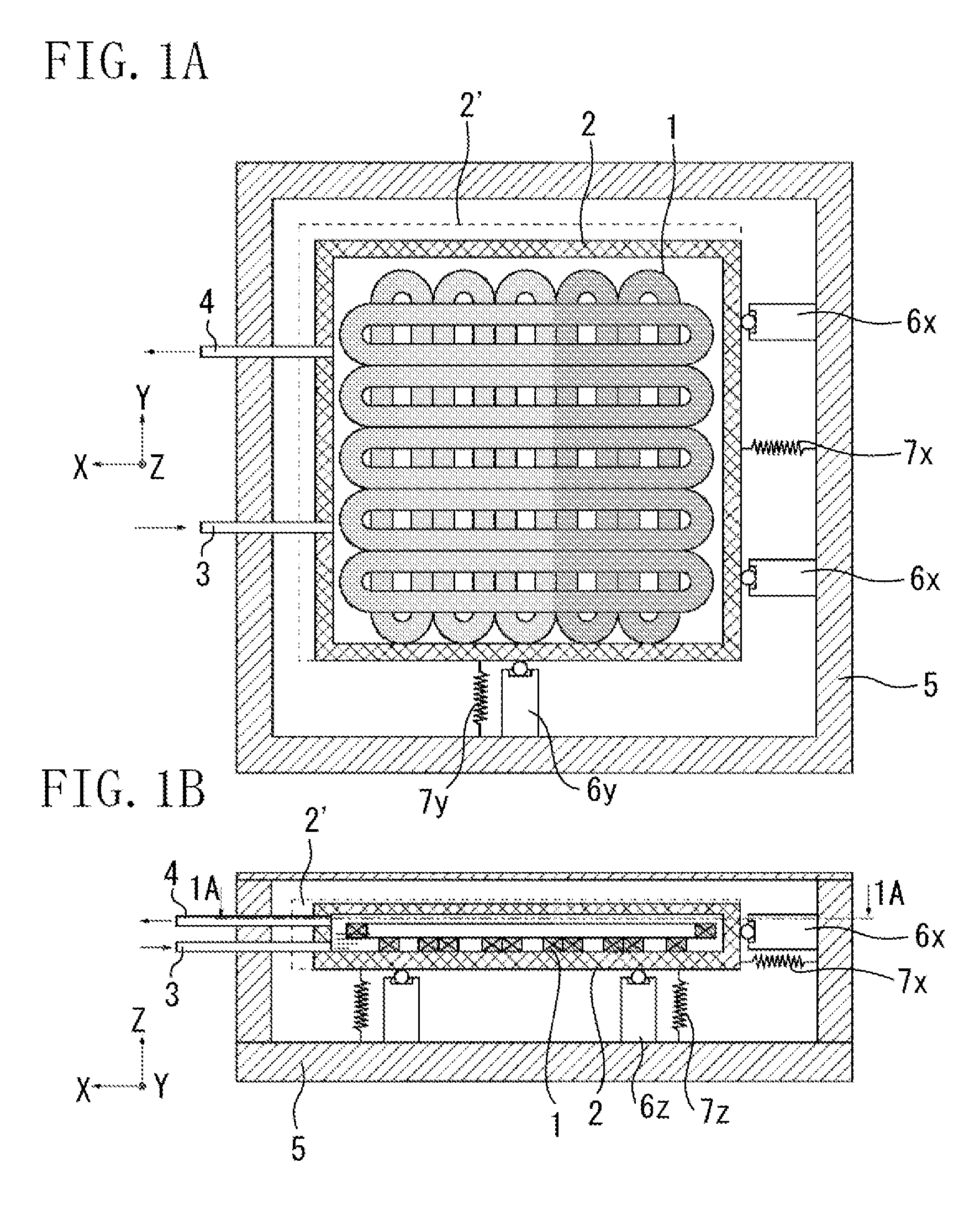
[0040]FIGS. 1A and 1B illustrate a configuration of a driving apparatus according to a first exemplary embodiment of the present invention.

[0041]A coil 1 is cooled by a cooling unit to a predetermined temperature. The coil 1 is held by a coil holding member 2. Further, the coil 1 and the coil holding member 2 are contained and held by an outer chamber or container 5 configured so that the inside thereof can be maintained in a vacuum state. The coil holding member 2 is supported by a supporting member 6z movably in an X-direction, which serves as a first direction, and in a Y-direction, which serves as a second direction. Moreover, the driving apparatus includes a first restriction member 6x, which restricts the movement in the X-direction (first direction) of the coil holding member 2, and a second restriction member 6y, which restricts the movement in the Y-direction (second direction) of the coil holding member 2. The first restriction member 6x supports the coil holding member 2 ...

second exemplary embodiment

[0076]FIG. 8 illustrates a configuration of a driving apparatus according to a second exemplary embodiment of the present invention.

[0077]As illustrated in FIG. 8, a coil (not shown) fixedly held in the coil holding member 2 is cooled by a cooling unit (not shown) to a desired temperature. The coil holding member 2 is held in the outer container (chamber) 5. In the configuration illustrated in FIG. 8, the coil holding member 2 is supported by three plate springs 18, each of which is adapted so that the stiffness thereof in one direction is lower than the stiffness thereof in the other two directions. The three plate springs 18 are disposed in an equally-spaced manner such that a low-stiffness direction, in which stiffness is lower than stiffness in the other directions, of each plate spring 18 forms an angle of substantially 120 degrees with a low-stiffness direction, in which stiffness is lower than stiffness in the other directions, of each of the other two plate springs 18.

[0078]...

third exemplary embodiment

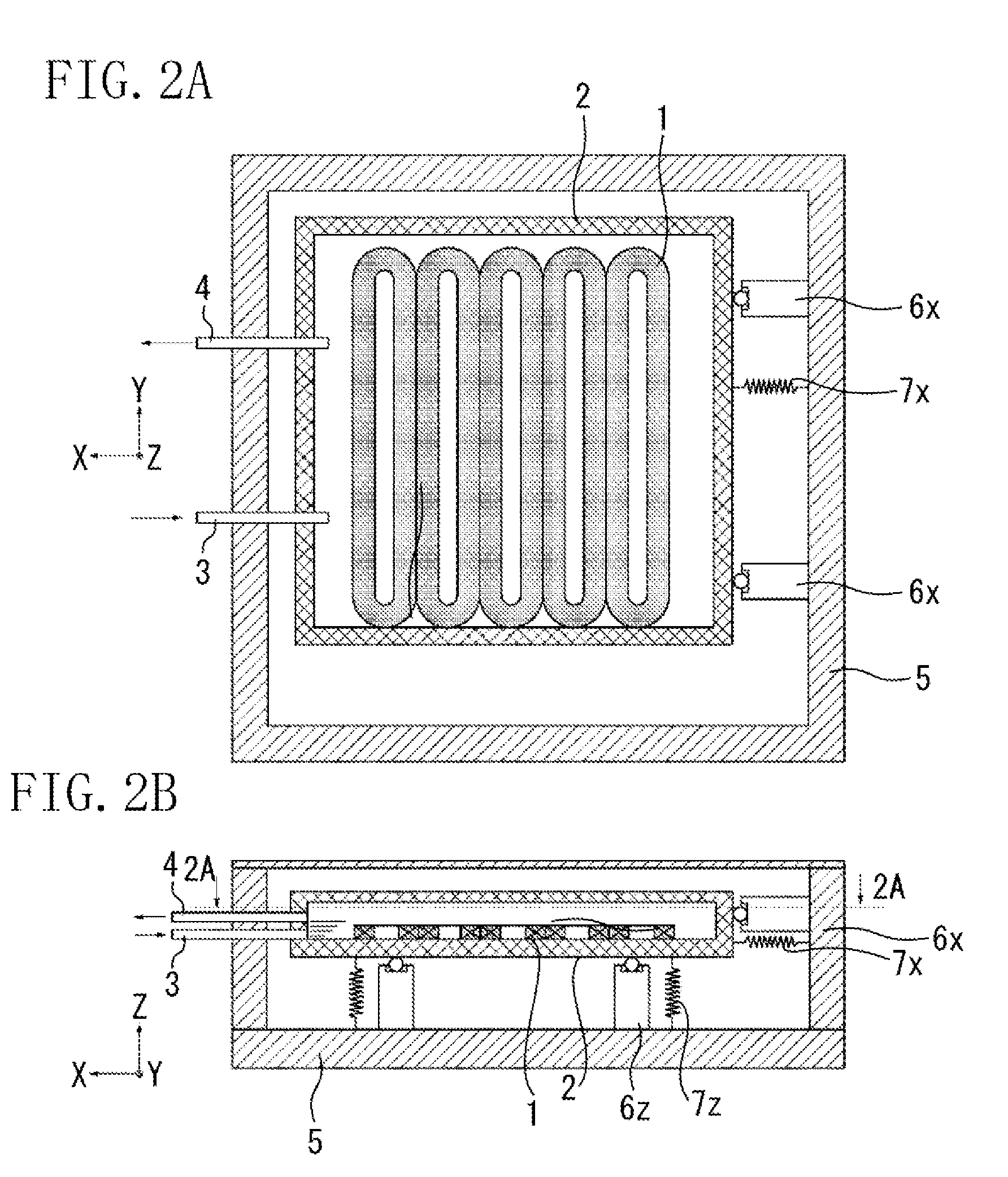
[0082]FIGS. 9A and 9B illustrate a configuration of a driving apparatus according to a third exemplary embodiment of the present invention. The coil 1 is cooled by a cooling unit to a desired temperature. Then, the coil 1 is held by the coil holding member 2 and is held in the outer container 5. The coil holding member 2 is supported by a supporting member 6z movably in an X-direction, which corresponds to the first direction, and a Y-direction, which corresponds to the second direction. The apparatus further includes a first restriction member 6x for restricting the movement in the X-direction, which corresponds to the first direction, and a second restriction member 6y for restricting the movement in the Y-direction, which corresponds to the second direction. The first restriction member 6x supports the coil holding member 2 movably in the Y-direction (second direction). The second restriction member 6y supports the coil holding member 2 movably in the Y-direction (second directio...


PUM


Abstract

A driving apparatus includes a mover having a magnet, and a stator having a coil. The driving apparatus is adapted to control the electric current to be applied to the coil to cause relative movement between the mover and the stator. The stator includes a coil holding member configured to hold the coil, a supporting member configured to support the coil holding member movably in first and second directions, a restriction member configured to restrict movement of the coil holding member in the first direction and to allow movement of the coil holding member in the second direction, and a biasing unit configured to press the coil holding member against the restriction member.

Description

BACKGROUND OF THE INVENTION[0001]1. Field of the Invention[0002]The present invention relates to a driving apparatus, an exposure apparatus utilizing the driving apparatus, and a device manufacturing method utilizing the exposure apparatus.[0003]2. Description of the Related Art[0004]A semiconductor exposure apparatus for transferring a pattern formed on a reticle onto a substrate, such as a wafer, onto which resist is applied, is used in a lithographic process for manufacturing devices such as semiconductor devices and liquid crystal display devices.[0005]Japanese Patent Application Laid-Open No. 2004-254489 discusses a stage apparatus for positioning a wafer and a reticle at predetermined places in an in-plane direction. FIGS. 14A and 14B illustrate a planar motor type stage apparatus discussed in Japanese Patent Application Laid-Open No. 2004-254489. This stage apparatus includes mover magnets 114 and a stator 100. The mover magnets 114 are arranged periodically in a plate-like s...

Claims


Application Information

Patent Timeline
Patent Type & Authority Applications(United States)
IPC IPC(8): H02K41/035
CPCH02K1/182H02K3/24H02K9/19Y02E40/62H02K55/00H02K2201/18H02K2213/09H02K41/031Y02E40/60G03F7/70758H01L21/027
Inventor ITO, ATSUSHI
Owner CANON KK
Why Eureka
Try Eureka