Electric motor control apparatus

a technology of electric motors and control apparatuses, applied in the direction of electric controllers, ignition automatic control, instruments, etc., can solve the problems of difficulty in simultaneously realizing an improvement in disturbance suppression force and vibration of load machines, and achieve the effect of suppressing disturbance in velocity control and improving disturbance suppression for

Inactive Publication Date: 2009-03-05
MITSUBISHI ELECTRIC CORP
View PDF9 Cites 25 Cited by
  • Summary
  • Abstract
  • Description
  • Claims
  • Application Information

AI Technical Summary

Benefits of technology

[0011]There are not required special means for performing calculation to obtain information relating to the mechanical system including the electric motor and the load machine and for identifying a frequency characteristic, and independently of adjustment of a velocity proportional gain and a velocity integral gain to suppress disturbance in the velocity control of the electric motor and the load ma

Problems solved by technology

However, there has been a problem that because of low rigidity of the torque transmission mechanism to couple the electric motor and the

Method used


Image

  • Electric motor control apparatus
  • Electric motor control apparatus
  • Electric motor control apparatus

Examples


embodiment 2

[0075]FIG. 5 is a block diagram showing an electric motor control apparatus of embodiment 2.

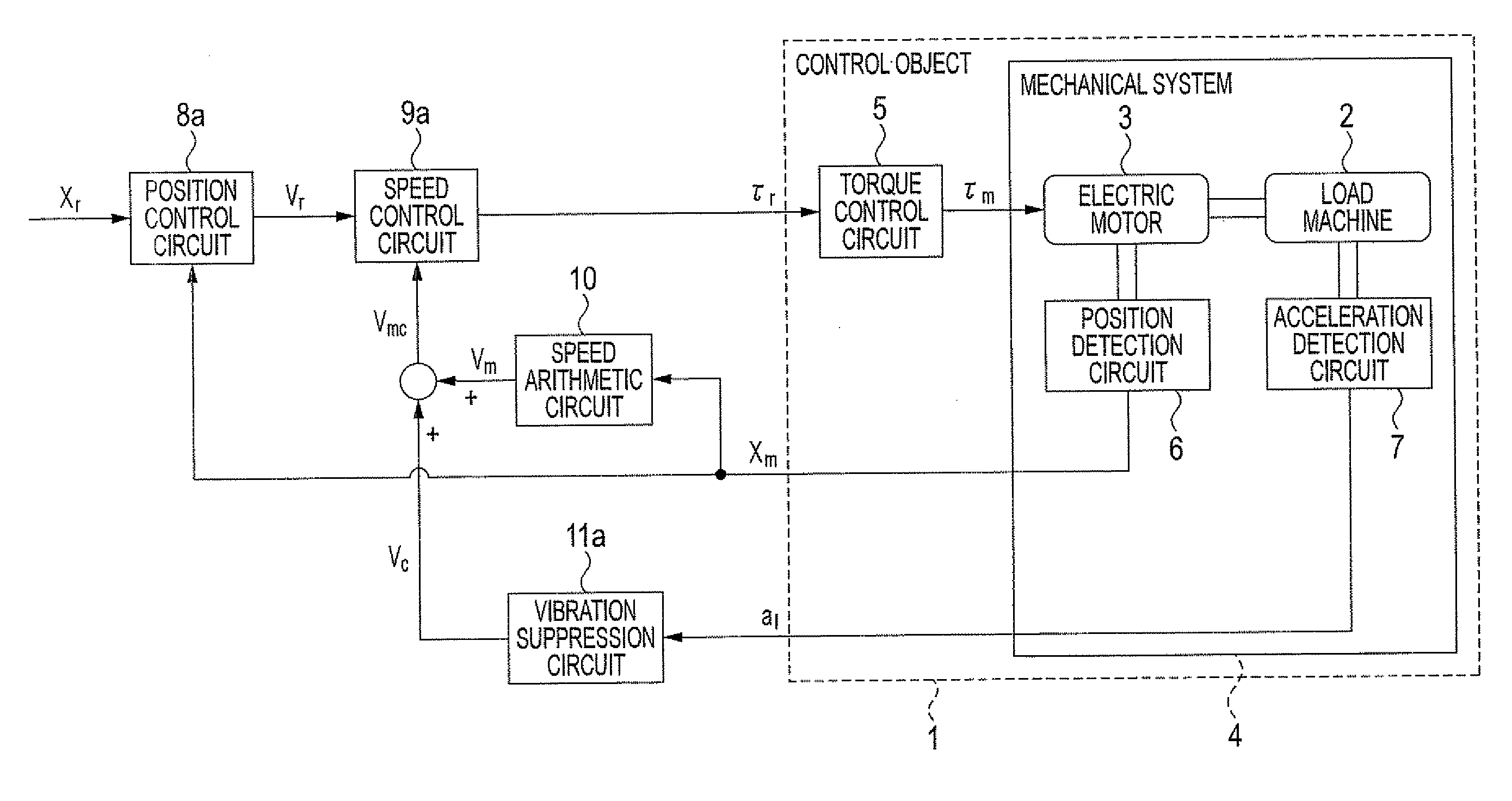
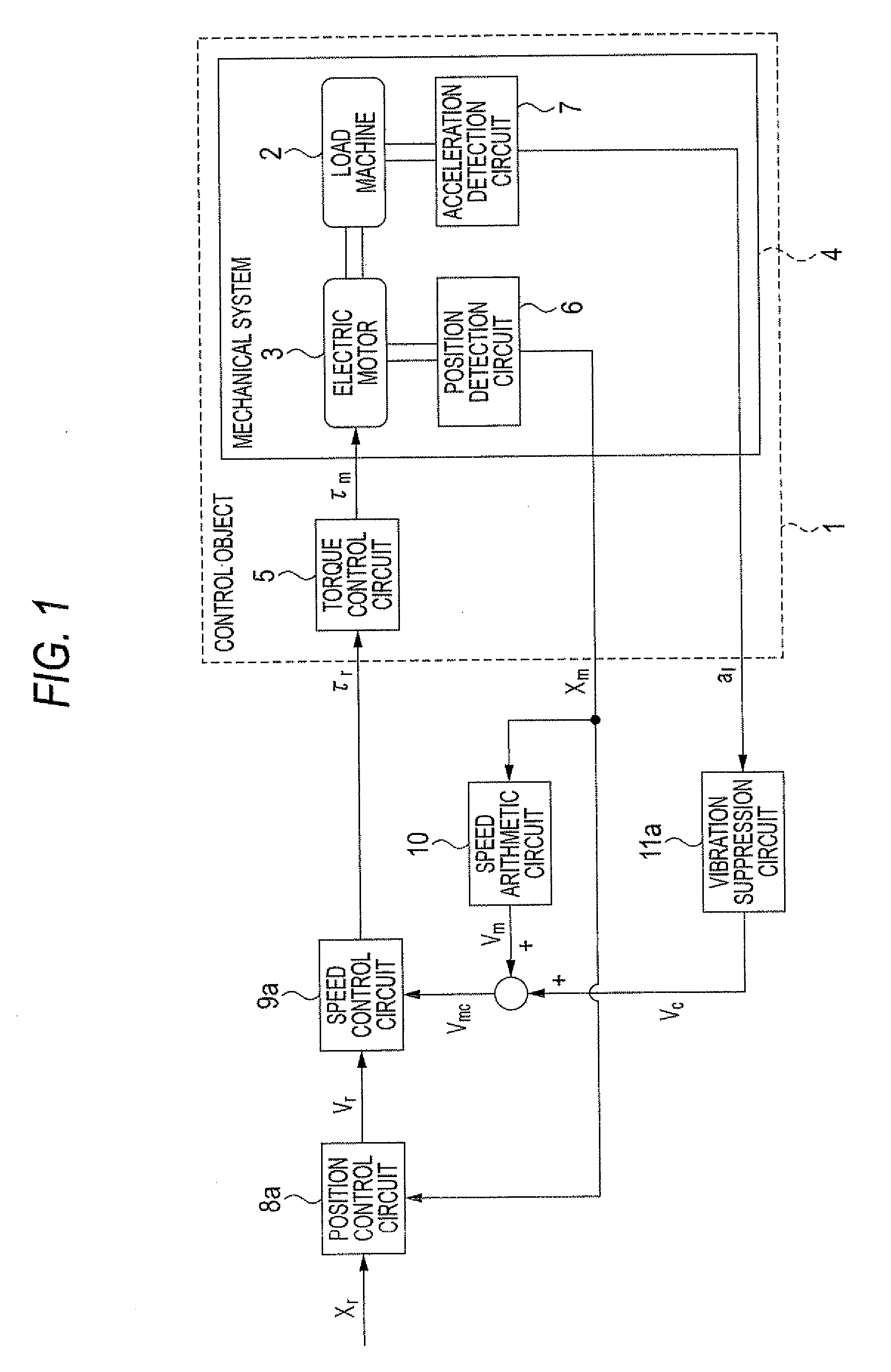
[0076]A control object 1 is the same as that of the embodiment 1.

[0077]A position control circuit 8c inputs a position command signal xr and a corrected position signal xmc obtained by adding a position signal xm and a position correction signal xc to correct the position signal xm, and outputs a velocity command signal vr.

[0078]A velocity control circuit 9c inputs the velocity command signal vr outputted by the position control circuit 8c and a velocity signal vm outputted by the velocity calculate circuit 10 performing an calculate operation on the position signal xm, and outputs a torque command signal τr.

[0079]The position correction signal xc is outputted by the vibration suppression circuit 11c which inputs an acceleration signal al of a load machine 2, and a transfer function of this vibration suppression circuit 11c is determined such that a transfer function from the acceleration sig...

embodiment 3

[0097]FIG. 7 is a block diagram showing an electric motor control apparatus of embodiment 3 of the invention. A control object 1 is the same as that of the embodiment 1.

[0098]A position control circuit 8e inputs a position command signal xr and a corrected position signal xmc obtained by adding a position signal xm of an electric motor 3 and a position correction signal xc to correct the position signal xm, and outputs a velocity command signal vr.

[0099]A velocity control circuit 9e inputs the velocity command signal vr outputted by the position control circuit 8e and a corrected velocity signal vmc obtained by adding a velocity signal vm outputted by a velocity calculate circuit 10 performing an calculate operation on the position signal xm and a velocity correction signal vc to correct the velocity signal vm, and outputs a torque command signal τr.

[0100]Although a vibration suppression circuit 11e outputs the position correction signal xc and the velocity correction signal vc, and...

embodiment 4

[0116]FIG. 8 is a view showing an electric motor control apparatus of embodiment 4 of the invention.

[0117]A control object is the same as that of the embodiment 1.

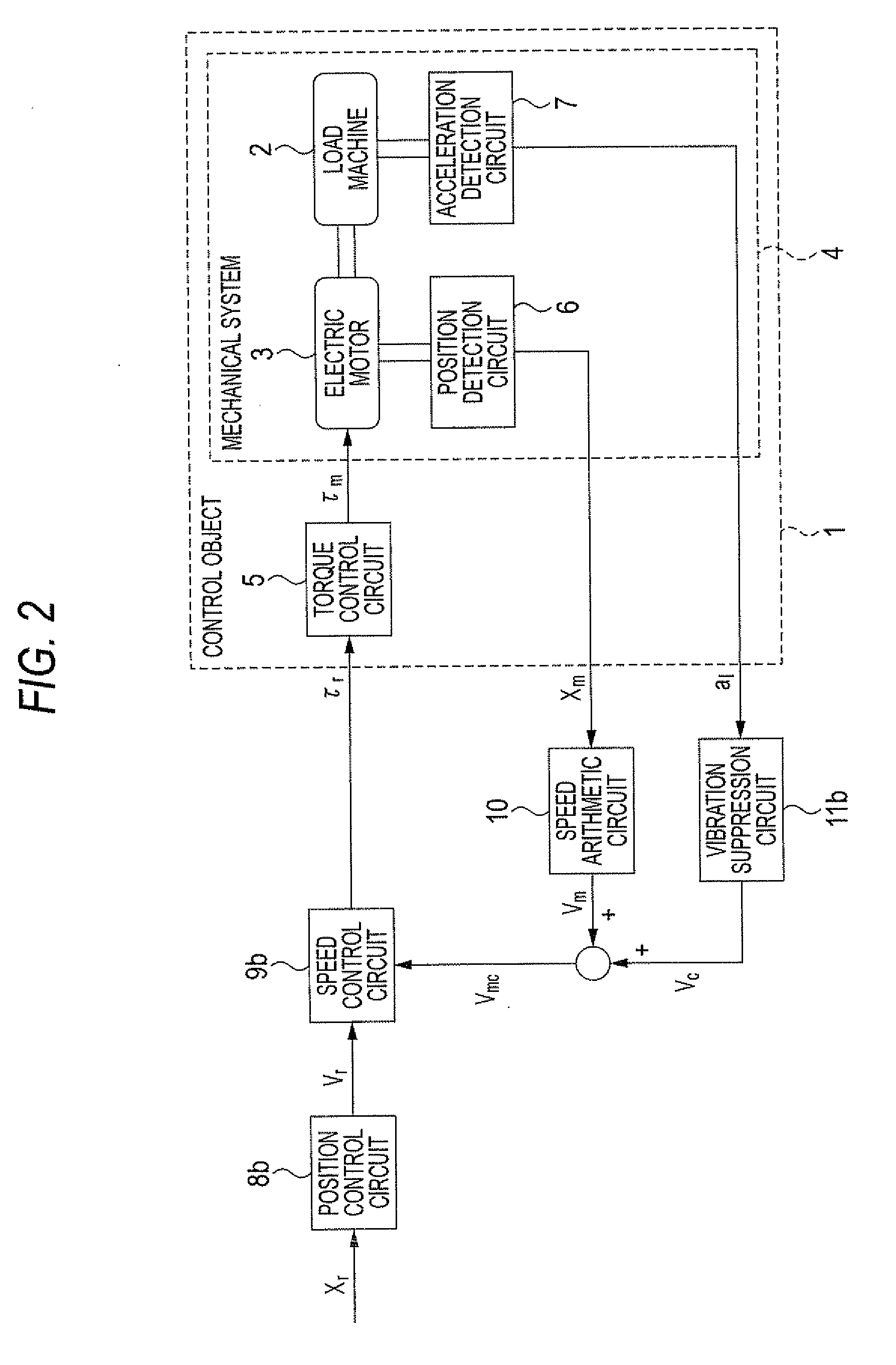
[0118]On the other hand, in the embodiments 1 to 3, the vibration suppression circuits 11a to 11e input the acceleration signal al of the load machine 2, and outputs the position correction signal xc to correct the position signal xm or the velocity correction signal vc to correct the velocity signal vm, however, in the embodiment 4, a vibration suppression circuit 11f is constructed to input an acceleration signal al and to output a torque correction signal τc to correct a torque command signal τv outputted by a velocity control circuit 9f.

[0119]A position control circuit 8f inputs a position command signal xr, and outputs a velocity command signal vr.

[0120]The velocity control circuit 9f inputs the velocity command signal vr outputted by the position control circuit 8f and a velocity signal vm outputted by a velocity ca...


PUM


Abstract

In order to simultaneously realize an improvement in disturbance suppression force of an electric motor control apparatus and vibration suppression of a load machine, a velocity control circuit receives a velocity command signal as a target value of velocity of an electric motor and a corrected velocity signal, obtained by correcting a velocity signal with a velocity correction signal, and outputs a torque command signal specifying target torque of the electric motor driving the load machine. A vibration suppression circuit outputs a velocity correction signal, based on an acceleration signal, indicating acceleration of the load machine. A transfer function from the acceleration signal to the torque command signal is obtained by multiplying a transfer function from a position signal, indicating position of the electric motor to the torque command signal, by a proportion characteristic having a specified gain and integration characteristic.

Description

TECHNICAL FIELD[0001]The present invention relates to an electric motor control apparatus to control an electric motor for driving a load machine such as a table of a machine tool or an arm of an industrial robot.BACKGROUND ART[0002]As this kind of electric motor control apparatus, there is known one in which control is performed by a torque command signal generated based on a velocity signal or a position signal of an electric motor so that the torque of the electric motor coincides with the torque command signal, and a load machine connected to the electric motor through a torque transmission mechanism is driven. However, there has been a problem that because of low rigidity of the torque transmission mechanism to couple the electric motor and the load machine, it is difficult to simultaneously realize an improvement in disturbance suppression force and vibration of the load machine.[0003]Then, a conventional electric motor control apparatus is constructed such that a signal obtai...

Claims


Application Information

Patent Timeline
IPC IPC(8): H02P31/00H02P29/00
CPCH02P29/0038G05D19/02H02P29/50G05D13/62
Inventor MARUSHITA, YOSHIHIROIKEDA, HIDETOSHIMATSUMOTO, KOKI
Owner MITSUBISHI ELECTRIC CORP
Why Eureka
Try Eureka