Frequency Tunable Filter

a filter and frequency technology, applied in the field of tunable filters, can solve the problems of difficult locking of the tuning bolt location, long time, labor and manufacturing costs, etc., and achieve the effect of preventing friction and minimizing friction with the cover

Active Publication Date: 2009-03-05
ACE TECH
View PDF7 Cites 36 Cited by
  • Summary
  • Abstract
  • Description
  • Claims
  • Application Information

AI Technical Summary

Benefits of technology

[0030]Also preferably, the ground member may include wings having an elastic body for contacting a cover of the filter. In this case, the elastic body may include a leaf spring. Also, in this case, a guide groove may be formed on the cover for guiding siding of the sliding member, the sliding member may be inserted in the guide groove, and the wings may be electrically coupled to the guide groove. Further, width of wings may be designed to be narrow sufficient to minimize friction with the cover.
[0031]Suitably, a plurality of friction prevention grooves may be formed on a lower part of the cover beside the guide groove for preventing friction between the metal tuning elements and the cover.

Problems solved by technology

When tuning is performed manually, it takes a long time because each of the tuning bolts 112 has to be rotated.
This becomes severe when there are many tuning bolts because each of the tuning bolts has to be rotated independently.
As a result, labor and manufacturing costs increase.
Also, after tuning is performed, it is hard to lock the location of the tuning bolts.
Tuning bolts tend to micro-rotate in the locking process, which results in failure of tuning.
In addition, it is hard to obtain a wide tuning range on account of high power trouble.
For smaller filters, obtaining a wide tuning range is more difficult.

Method used


Image

  • Frequency Tunable Filter
  • Frequency Tunable Filter
  • Frequency Tunable Filter

Examples


Embodiment Construction

[0056]Hereinafter reference will now be made in detail to various embodiments of the present invention, examples of which are illustrated in the accompanying drawings and described below. While the invention will be described in conjunction with exemplary embodiments, it will be understood that present description is not intended to limit the invention to those exemplary embodiments. On the contrary, the invention is intended to cover not only the exemplary embodiments, but also various alternatives, modifications, equivalents and other embodiments, which may be included within the spirit and scope of the invention as defined by the appended claims.

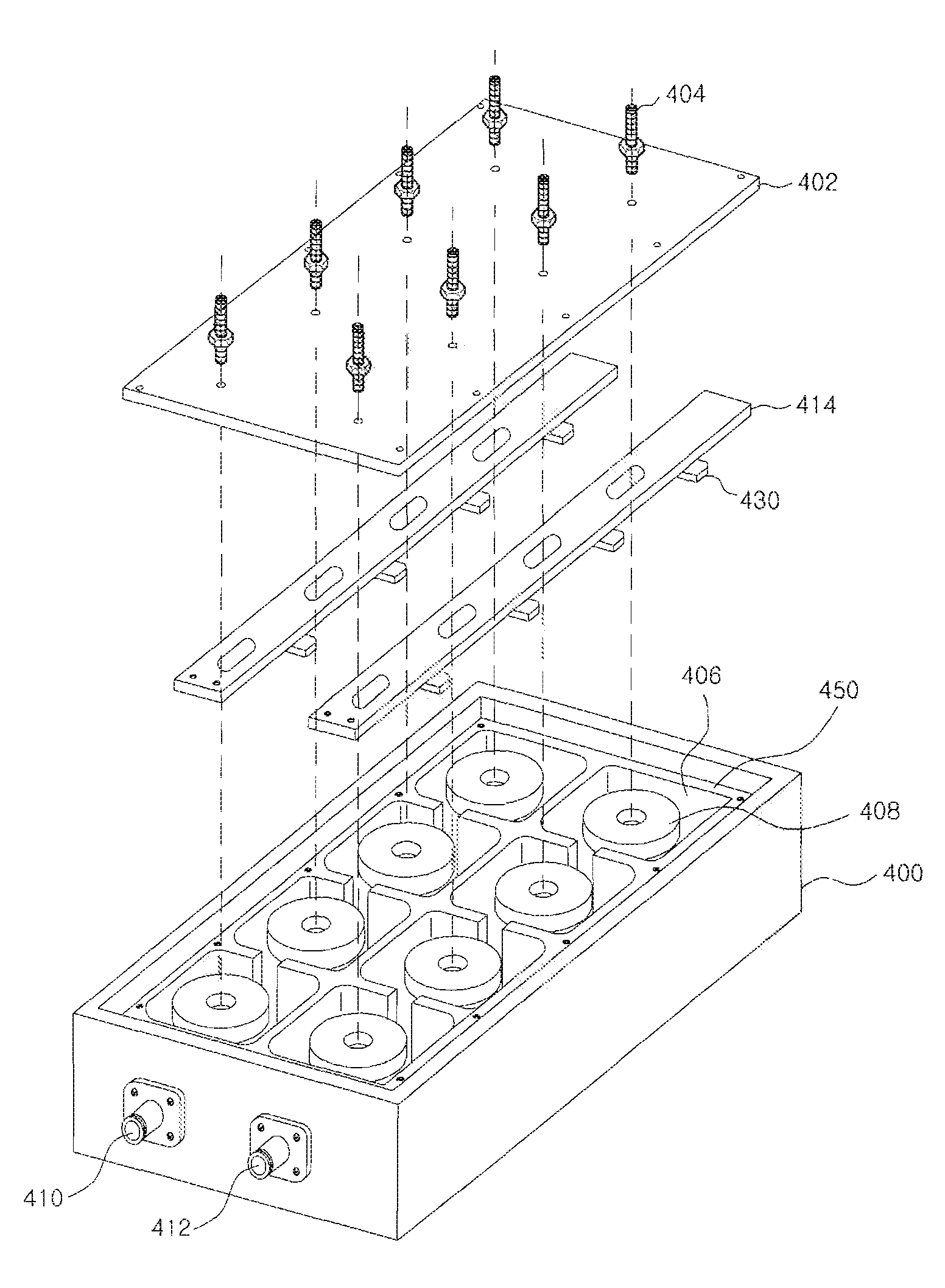
[0057]FIG. 4 is a disjointed perspective view of a frequency tunable filter according to a preferred embodiment of the present invention. The frequency tunable filter according to a preferred embodiment of the present invention may comprise a housing 400, a cover 402, a plurality of tuning bolts 404, a plurality of cavities 406, a plurali...


PUM


Abstract

A frequency tunable filter comprises a housing having a plurality of walls therein defining a plurality of cavities; a cover mounted on the housing; a plurality of resonators contained in the cavities; at least one sliding member located between the cover and the resonators; and a plurality of metal tuning elements attached to a lower part of the sliding member, wherein frequency tuning is performed by sliding of the sliding member.

Description

CROSS-REFERENCE TO RELATED APPLICATION[0001]This application claims under 35 U.S.C. §119(a) the benefit of Korean Patent Application Nos. 10-2007-0086585, 10-2007-0086586 and 10-2007-0086587 filed Aug. 28, 2007, the entire contents of which are incorporated herein by reference.TECHNICAL FIELD[0002]The present invention relates to a tunable filter that can change characteristics of the filter including center frequency and bandwidth.BACKGROUND ART[0003]A filter is a device designed to pass a predetermined frequency band from an inputted RF signal. The filter has been realized in various ways. In case of an RF filter, a pass band is determined by inductance and capacitance of the filter. Tuning refers to adjusting a pass band of the filter.[0004]In a communication system such as a mobile communication system, a plurality of pass bands are allotted to communication service providers. Generally, the service providers divide the allotted pass bands into a plurality of channels. They use ...

Claims


Application Information

Patent Timeline
Patent Type & Authority Applications(United States)
IPC IPC(8): H01P1/208
CPCH01P7/04H01P1/2053
Inventor SEO, JAE OKLEE, SUK WOOCHUN, DONG WANKIM, JIN YANGPARK, KWANG SUN
Owner ACE TECH
Why Eureka
Try Eureka