Signal processing device for biological observation apparatus

Active Publication Date: 2009-03-05
OLYMPUS CORP
View PDF12 Cites 45 Cited by
  • Summary
  • Abstract
  • Description
  • Claims
  • Application Information

AI Technical Summary

Benefits of technology

[0012]A signal processing device for a biological observation apparatus according to a first aspect of the present invention is a signal processing device for a biological observation apparatus comprising an illumination unit for irradiating light to a living body that is a test subject, and/or a signal processing control unit for photoelectrically converting light reflected from the living body based on illumination light from the illumination unit, controlling an operation of an

Problems solved by technology

However, for example, in the apparatus disclosed in the above described Japanese Patent Laid-Open No. 2003-93336, an spectral image is obtained by signal processing, and a filter for generating narrow band RGB light is not required, but since the obtained spectral image is simply outputted to a monitor, ther

Method used


Image

  • Signal processing device for biological observation apparatus
  • Signal processing device for biological observation apparatus
  • Signal processing device for biological observation apparatus

Examples


embodiment 1

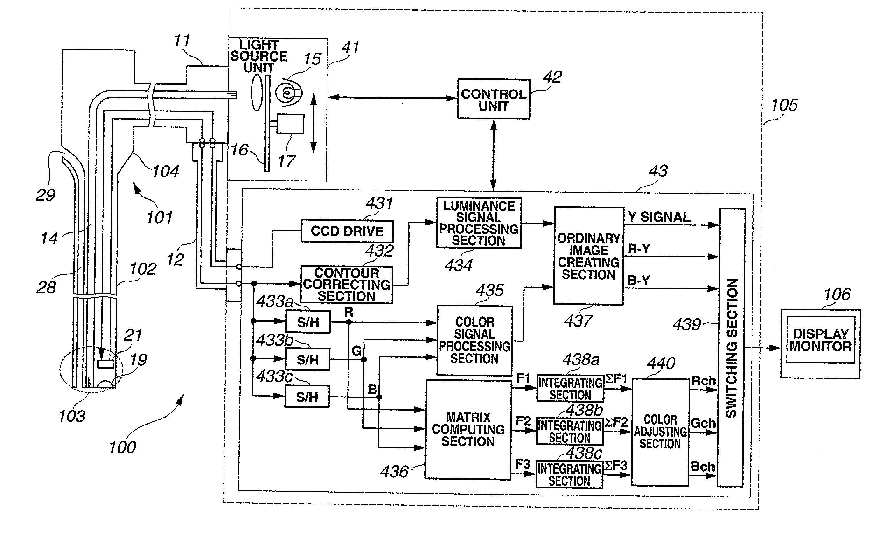
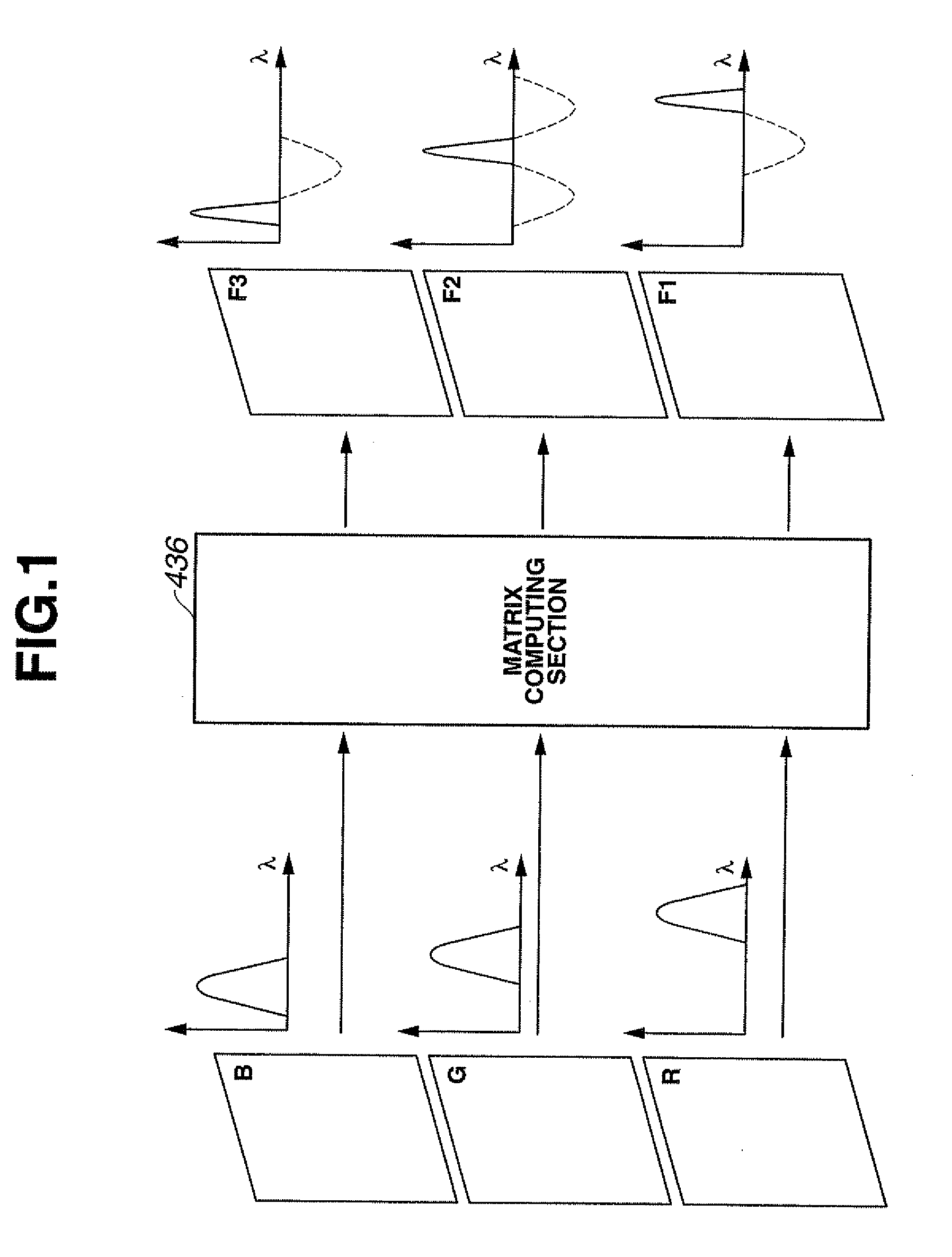
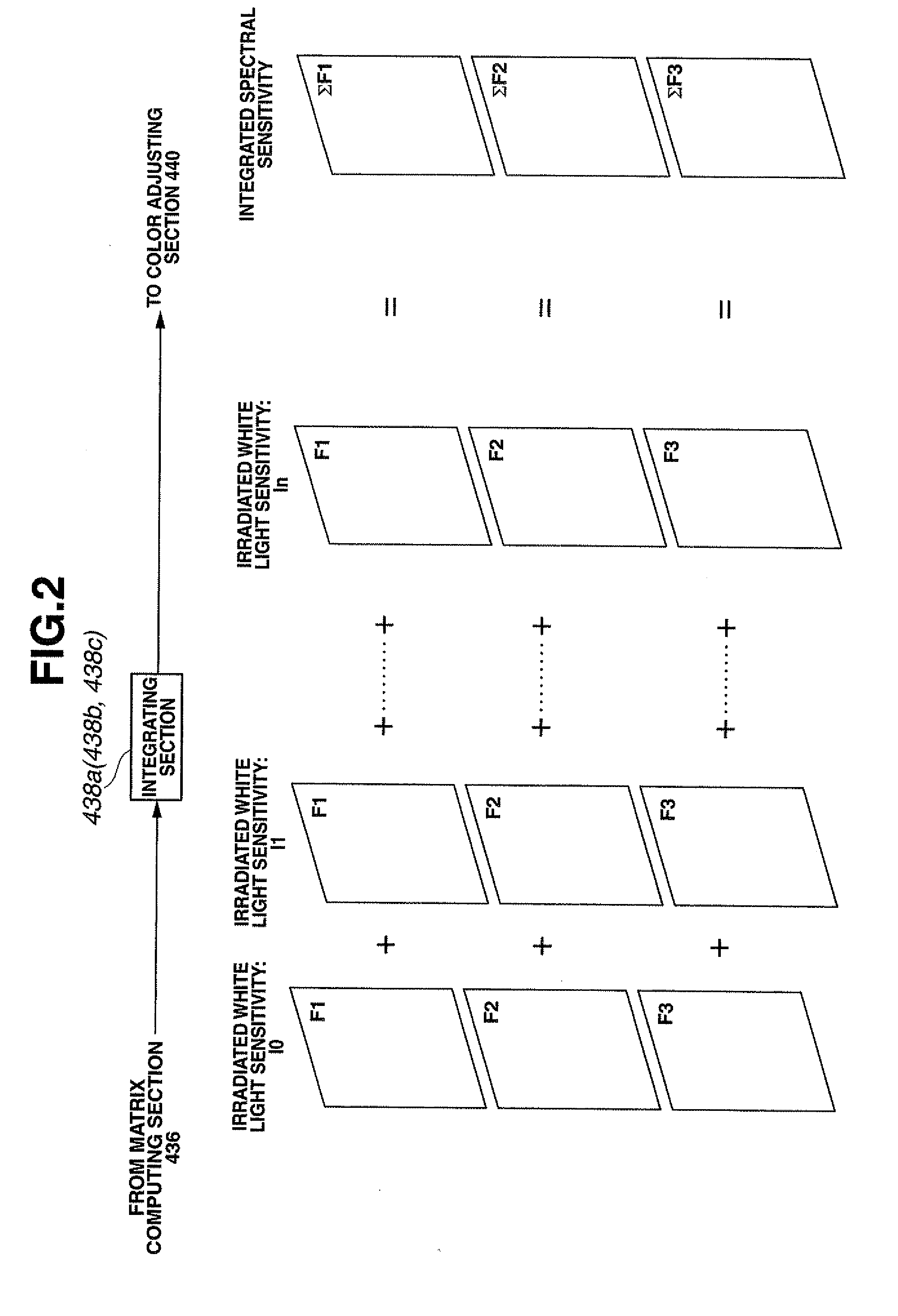
[0066]FIGS. 1 to 26 relate to an embodiment 1 of the present invention. FIG. 1 is a conceptual diagram showing a flow of a signal when creating a spectral image signal from a color image signal. FIG. 2 is a conceptual diagram showing integrating computation of the spectral image signal. FIG. 3 is an exterior view showing an appearance of an electronic endoscope apparatus. FIG. 4 is a block diagram showing a configuration of the electronic endoscope apparatus of FIG. 3. FIG. 5 is an exterior view showing an appearance of a chopper of FIG. 4. FIG. 6 is a diagram showing an arrangement of color filters disposed on an image pickup surface of a CCD of FIG. 3. FIG. 7 is a diagram showing spectral sensitivity characteristics of the color filters of FIG. 6. FIG. 8 is a configuration diagram showing a configuration of a matrix computing section of FIG. 4. FIG. 9 is a spectrum diagram showing a spectrum of a light source. FIG. 10 is a spectrum diagram showing a reflection spectrum of a living...

embodiment 2

[0209]FIG. 27 is a block diagram showing a configuration of an electronic endoscope apparatus according to an embodiment 2 of the present invention.

[0210]Since the embodiment 2 is substantially the same as the embodiment 1, only the different point will be described, and the explanation of the same components will be omitted by being assigned with the same reference numerals and characters as in the first embodiment.

[0211]The present embodiment mainly differs from the embodiment 1 in the light source unit 41 which performs control of the illumination light quantity. In the present embodiment, control of the light quantity irradiated from the light source unit 41 is performed by current control of the lamp 15 instead of the chopper. More specifically, a current control section 18 is provided at the lamp 15 shown in FIG. 27.

[0212]As an operation of the present embodiment, the control unit 42 controls the current control section 18 and performs control of a current flowing into the lam...

embodiment 3

[0215]FIG. 28 is a block diagram showing a configuration of a matrix computing section according to an embodiment 3.

[0216]Since the embodiment 3 is substantially the same as the embodiment 1, only the different point will be described, and the explanation of the same components will be omitted by assigning them with the same reference numerals and characters as the embodiment 1.

[0217]The present embodiment differs from the embodiment 1 mainly in the configuration of the matrix computing section 436. In the embodiment 1, the matrix computation is performed by so-called hardware processing by the electronic circuit, but in the present embodiment of FIG. 28, the matrix computation is performed by numeric data processing (processing by software using a program).

[0218]A concrete configuration of the matrix computing section 436 in the present embodiment is shown in FIG. 28. The matrix computing section 436 has an image memory 50 which stores respective color image signals of R, G and B. ...


PUM


Abstract

Tissue information of a desired deep portion of a biological tissue based on a spectral image obtained from signal processing is adjusted to image information in a color tone suitable for observation. Outputs of a matrix computing section 436 are respectively connected to integrating sections 438a to 438c, and after integrating computation is performed for them, color conversion computation is performed for respective spectral image signals ΣF1 to ΣF3 in a color adjusting section 440, spectral color channel image signals Rch, Gch and Bch are created from the spectral image signals ΣF1 to ΣF3, and images of the spectral color channel images Rch, Gch and Bch are sent to a display monitor 106 via a switching section 439.

Description

TECHNICAL FIELD[0001]The present invention relates to a signal processing device for a biological observation apparatus which uses a color image signal obtained by picking up an image of a living body and displays the image on a monitor as a spectral image by signal processing.BACKGROUND ART[0002]Conventionally, as a biological observation apparatus, an endoscope apparatus which irradiates illumination light and obtains an endoscope image in a body cavity has been widely used. In an endoscope apparatus of this kind, an electronic endoscope having image pick up means which guides illumination light from a light source into a body cavity by using a light guide or the like and picks up an image of a subject by its feedback light, and by performing signal processing of an image pickup signal from the image pickup means by a video processor, the endoscope image is displayed on an observation monitor so that an observation region of a patient or the like is observed.[0003]When ordinary bi...

Claims


Application Information

Patent Timeline
IPC IPC(8): A61B1/04
CPCA61B1/00186A61B1/045A61B1/0638A61B1/0646A61B5/0075A61B5/0084G01J3/32G01J3/50G01J3/501G01J3/513G01J2003/1213G01J2003/1221G01N21/255G02B23/24A61B5/7242A61B1/000094A61B1/0655H04N23/555A61B1/00A61B1/04H04N7/18
Inventor GONO, KAZUHIROAMANO, SHOICHITAKAHASHI, TOMOYAOHSHIMA, MUTSUMI
Owner OLYMPUS CORP
Why Eureka
Try Eureka