Full-Field Light Detection and Ranging Imaging System

a full-field light detection and imaging system technology, applied in the field of imaging systems, can solve the problems of cost and technology windfall, time-critical requirements are even more demanding,

Active Publication Date: 2009-03-05
SCI APPL INT CORP
View PDF11 Cites 202 Cited by
  • Summary
  • Abstract
  • Description
  • Claims
  • Application Information

AI Technical Summary

Benefits of technology

[0016]With another aspect of the invention, when different positional information is obtained for different pixels in the image, the imaging system determines that different objects appear in the image. The imaging system may distinguish the different objects in a display presented to a user.

Problems solved by technology

For military combat vehicles, the time-critical requirements are even more demanding.
LIDAR cameras typically have a separate LIDAR detector since the imaging arrays have integration times that are too long for LIDAR data capture.
)The technology is highly developed and commercially expanding in optical communications, leading to both cost and technology windfalls.

Method used


Image

  • Full-Field Light Detection and Ranging Imaging System
  • Full-Field Light Detection and Ranging Imaging System
  • Full-Field Light Detection and Ranging Imaging System

Examples


Embodiment Construction

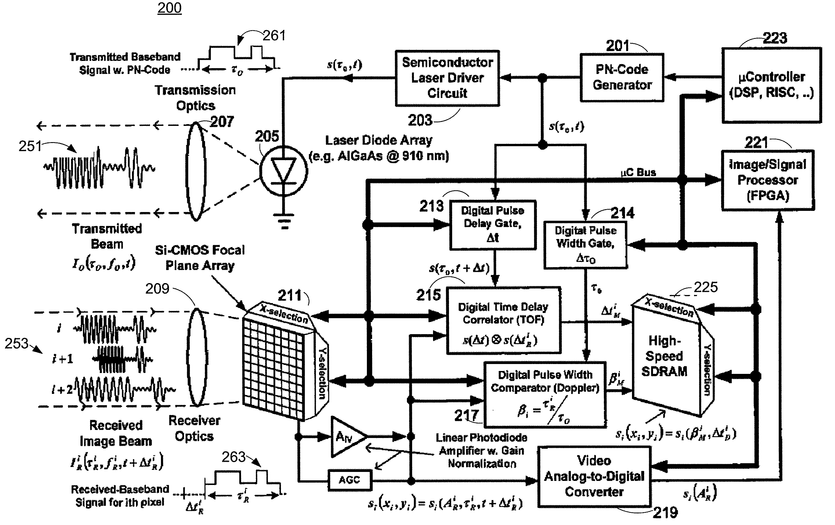
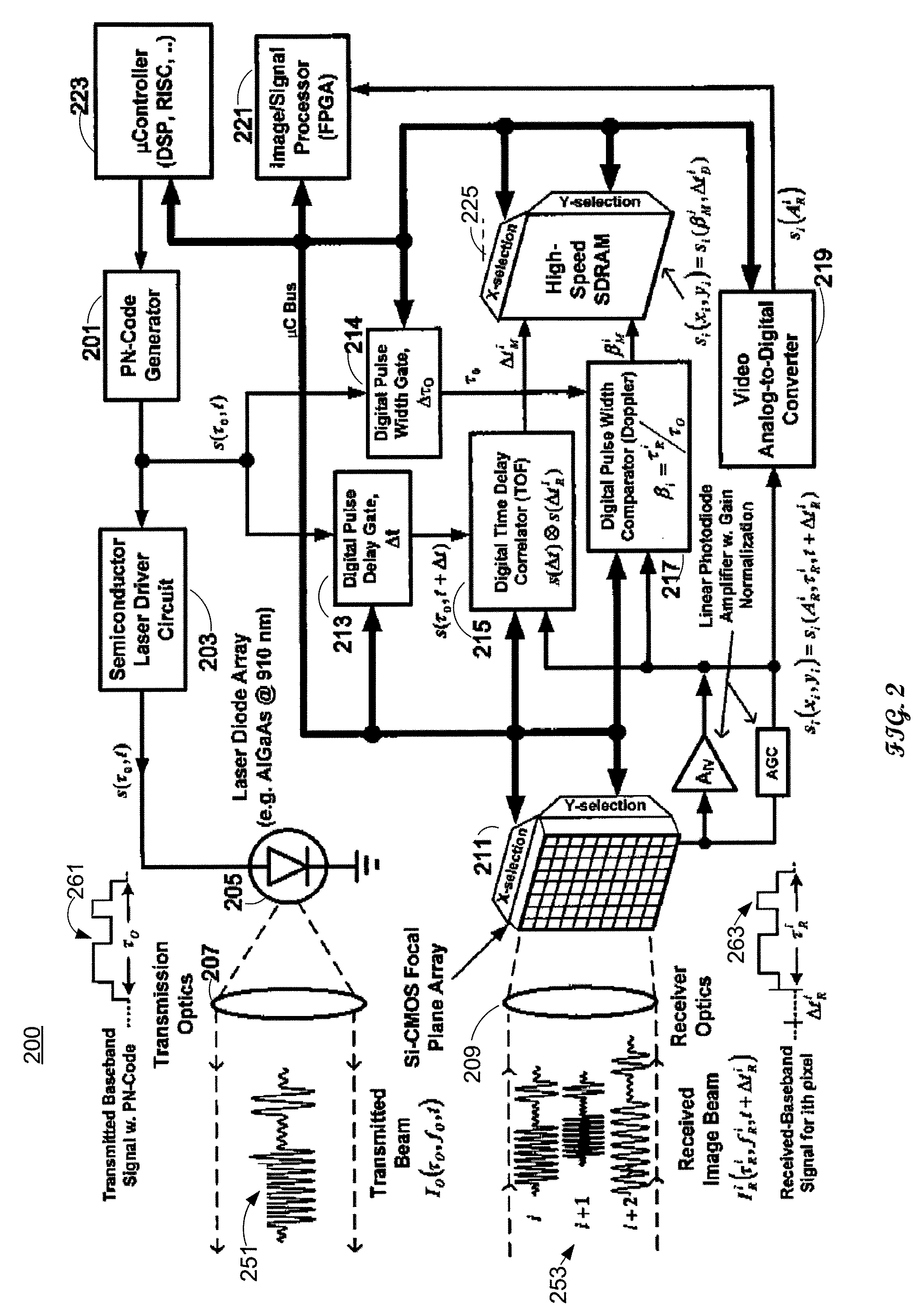
[0032]In the following description of the various embodiments, reference is made to the accompanying drawings which form a part hereof, and in which is shown by way of illustration various embodiments in which the invention may be practiced. It is to be understood that other embodiments may be utilized and structural and functional modifications may be made without departing from the scope of the present invention.

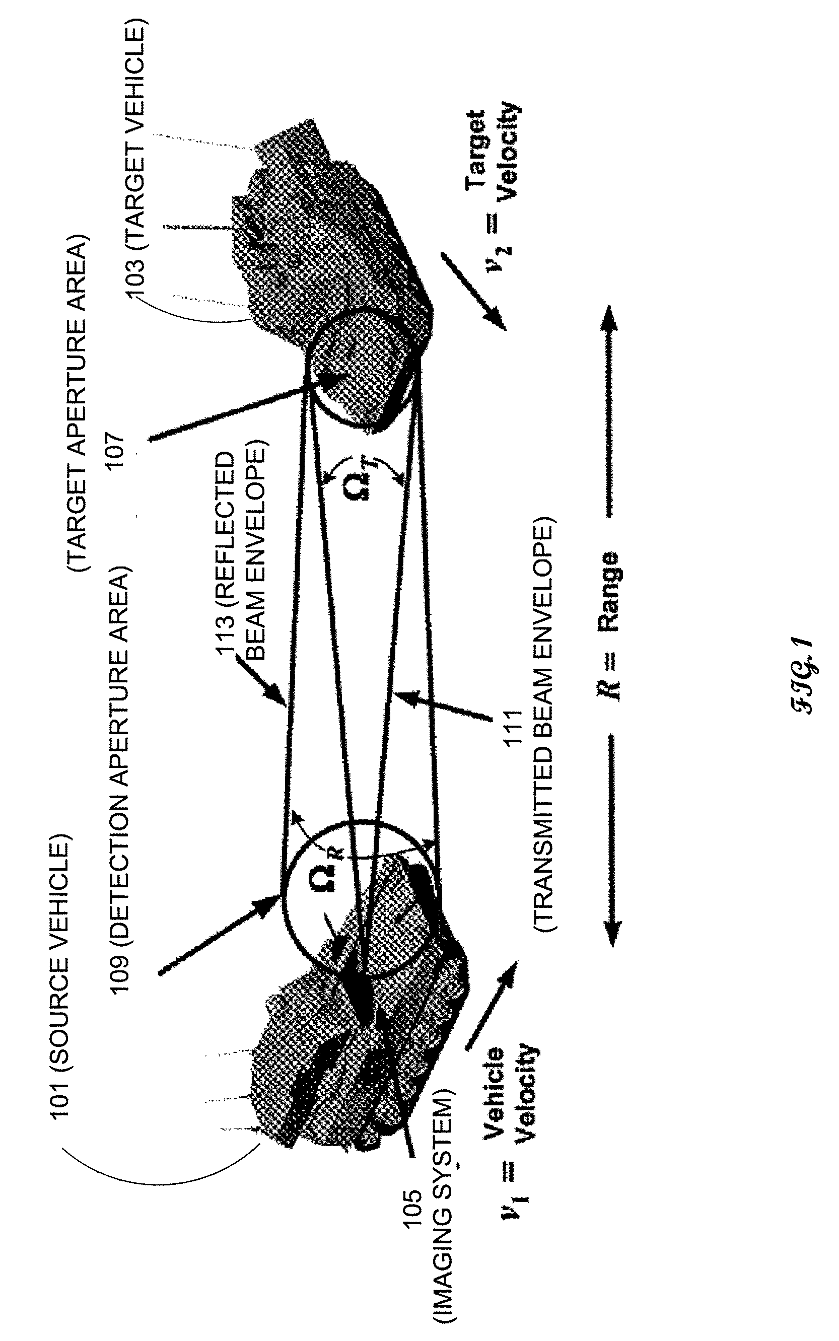
[0033]FIG. 1 shows an exemplary geometry of an imaging system in accordance with an embodiment of the invention. Source vehicle 101 is equipped with imaging system 105 for determining imaging and positional data for target vehicle 103. (Positional information may indicate a current position and / or projected position of target vehicle 103. For example, positional information may include a relative velocity and a range of target vehicle 103 with respect to source vehicle 101.) The geometry as shown in FIG. 1 is based on isotropic scattering and has essentially the same geome...


PUM


Abstract

Apparatuses and methods determine positional information from a reflected optical signal for an object on a per pixel basis. A spread spectrum imaging system includes a transmitting module transmitting a transmitted optical signal that illuminates a target space and contains a transmitted pulse that is modulated with a first pseudo-noise (PN) code. The imaging system includes a receiving module that receives a reflected optical signal from an object. The reflected signal is processed by an optical array that detects a detected signal from the reflected optical signal, where the detected signal contains a plurality of pixels spanning a target space. When the determined PN code corresponds to the selected PN code, image information and the positional information is presented for the object. When different positional information is obtained for different pixels in the image, the imaging system may determine that different objects appear in the received image.

Description

FIELD OF THE INVENTION[0001]The present invention relates to an imaging system that includes light detection and ranging (LIDAR) data for a pixel of imaging information.BACKGROUND OF THE INVENTION[0002]The United States military has designated mobile robotics and autonomous vehicle systems having a high priority for future combat and warfare, and consequently there is a strong demand for more intelligent and reliable vision sensor subsystems in today's tactical vehicles. Future combat vehicles will be highly dependent upon a wide variety of robust sensor technologies both inside the vehicle (monitoring occupant presence and position) as well as external to the vehicle (monitoring vehicle orientation, relative closing velocities, and potential obstacles).[0003]Prior art multi-camera vision systems typically used in military applications incorporate high resolution, silicon-based day-cameras, as well as infrared (EOIR) focal plane arrays. The far-infrared (FIR and LWIR) cameras typica...

Claims


Application Information

Patent Timeline
Patent Type & Authority Applications(United States)
IPC IPC(8): G01C3/08
CPCG01S7/491G01S17/32G01S7/4917G01S17/89G01S17/58G01S17/894
Inventor WILLNER, CHRISTOPHER ALLENMCDOWELL, JAMES
Owner SCI APPL INT CORP
Why Eureka
Try Eureka