Heat Sinks for Cooling LEDS in Projectors

a technology of heat sinks and projectors, which is applied in the field of image projectors, can solve the problems of not providing sufficient intensity and/or reliability of leds, controlling junction temperatures, etc., and achieve the effect of reducing the disadvantages and eliminating the problems of controlling the junction temperatures of light emitting diodes (leds)

Active Publication Date: 2009-03-05
TEXAS INSTR INC
View PDF13 Cites 49 Cited by
  • Summary
  • Abstract
  • Description
  • Claims
  • Application Information

AI Technical Summary

Benefits of technology

[0004]According to certain embodiments of the present invention, disadvantages and problems associated with controlling the junction temperatures of light emitting diodes (LEDs) may be reduced or eliminated.

Problems solved by technology

At certain junction temperatures, an LED might not provide light of sufficient intensity and / or reliability.
Accordingly, one challenge associated with LED image projectors is controlling the junction temperatures of the LEDs.

Method used


Image

  • Heat Sinks for Cooling LEDS in Projectors
  • Heat Sinks for Cooling LEDS in Projectors
  • Heat Sinks for Cooling LEDS in Projectors

Examples


Embodiment Construction

[0014]Example embodiments of the invention are best understood by referring to FIGS. 1 through 4 of the drawings, like numerals being used for like and corresponding parts of the various drawings.

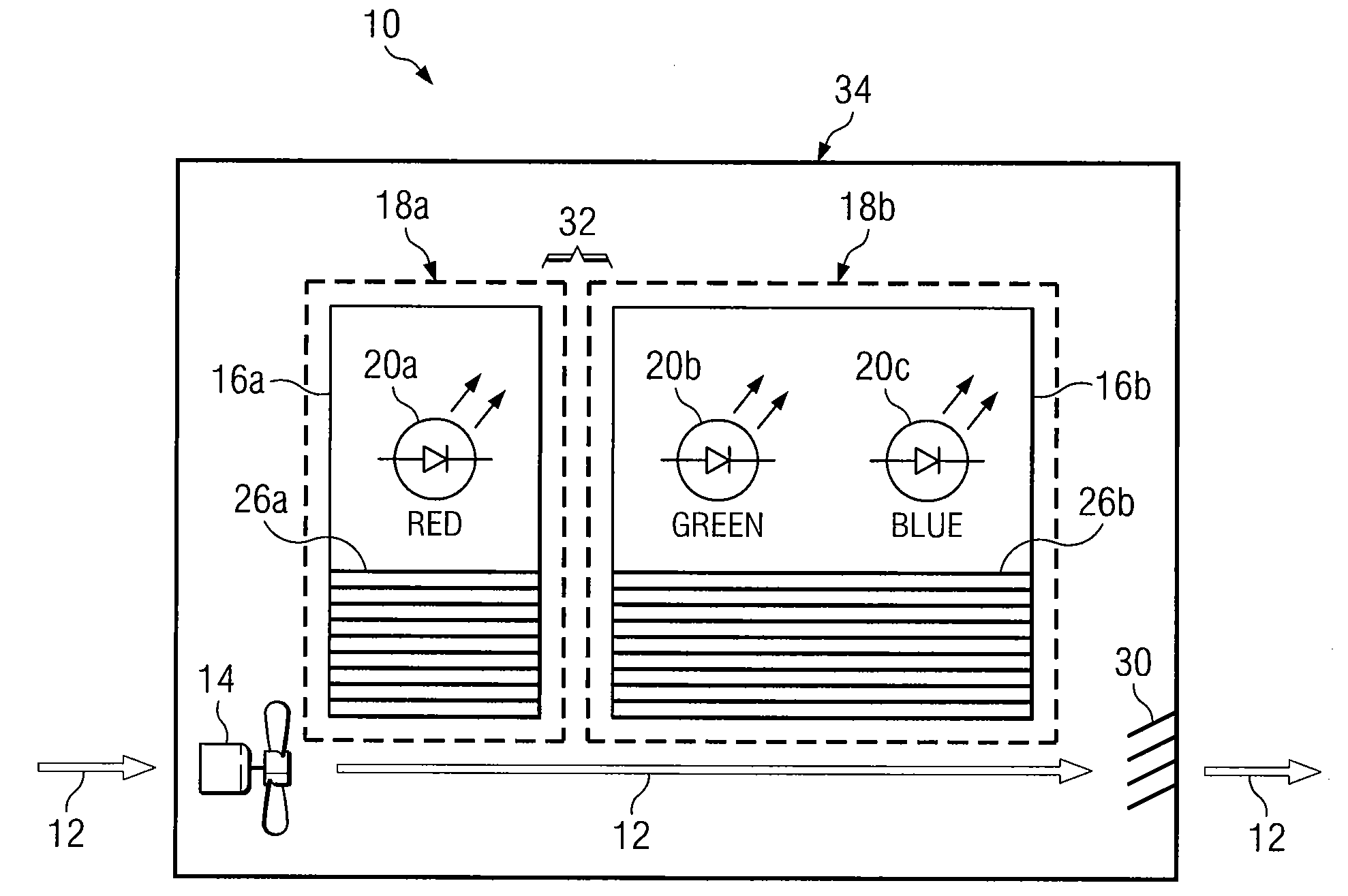
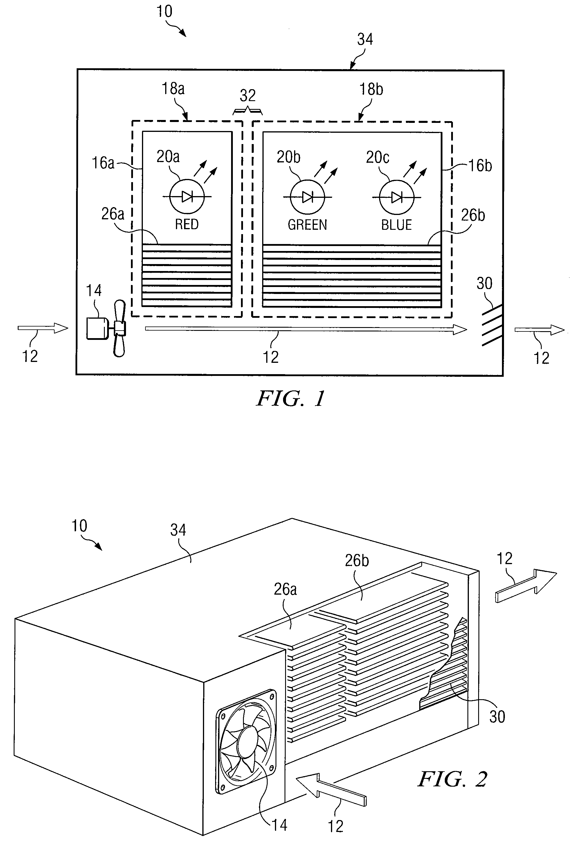
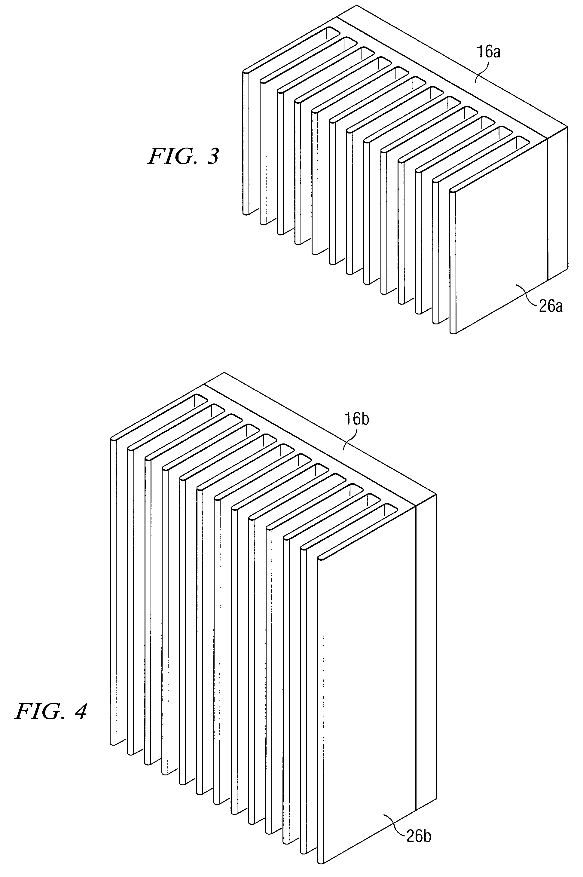
[0015]FIG. 1 is a block diagram illustrating an embodiment of an image projector 10. In the illustrated embodiment, projector 10 includes thermal subsystems 18 (18a, b). First thermal subsystem 18a includes one or more first light sources 20a (“light emitters” or “LEDs”) and one or more first heat dissipation units 26a (or “heat sinks”) coupled to a first circuit board 16a. First light source 20a is thermally coupled to first heat dissipation unit 26a. Second thermal subsystem 18b includes one or more second light sources 20b, 20c and one or more second heat dissipation units 26b coupled to a second circuit board 16b. Second light sources 20b, 20c are thermally coupled to second heat dissipation unit 26b. An air gap 32 is located between first thermal subsystem 18a and second thermal subsys...


PUM


Abstract

According to certain embodiments, an apparatus for cooling light emitting diodes (LEDs) in projectors includes one or more first LEDs, one or more first heat sinks, one or more second LEDs, and one or more second heat sinks. The first LEDs are configured to generate light, and each first LED has a first desired junction temperature. The first heat sinks are configured to dissipate heat generated by the first LEDs. The second LEDs are configured to generate light, and each second LED has a second desired junction temperature that is higher than the first desired junction temperature. The second heat sinks are configured to dissipate heat generated by the one or more second LEDs. A cooling fan directs air flow over the first heat sinks and the second heat sinks, and an exhaust vent enables the air flow over the first heat sinks and the second heat sinks.

Description

RELATED APPLICATION[0001]This application claims benefit under 35 U.S.C. §119(e) of U.S. Provisional Application Ser. No. 60 / 968,881, entitled “OPTIMIZED HEAT SINK SOLUTION TO COOL LEDS IN A SMALL FORM FACTOR PROJECTOR APPLICATION,” Attorney's Docket TI-65281PS, filed Aug. 29, 2007, by Amit A. Kulkarni.TECHNICAL FIELD[0002]This invention generally relates to image projectors and, more particularly, to heat sinks for cooling LEDs in projectors.BACKGROUND[0003]Image projectors display images on external surfaces. An image projector may display a single image or a series of images such as a video. Image projectors use a variety of light sources such as cathode ray tubes (CRTs), spatial light modulation devices, lasers, and light emitting diodes (LEDs). A typical LED image projector employs a red LED, a green LED, and a blue LED to generate light. At certain junction temperatures, an LED might not provide light of sufficient intensity and / or reliability. Accordingly, one challenge assoc...

Claims


Application Information

Patent Timeline
Patent Type & Authority Applications(United States)
IPC IPC(8): F21V33/00
CPCG03B21/16F28F3/02
Inventor KULKARNI, AMIT A.
Owner TEXAS INSTR INC
Why Eureka
Try Eureka