Object Distance Deriving Device

Inactive Publication Date: 2009-03-05
FUNAI ELECTRIC CO LTD +1
View PDF12 Cites 193 Cited by
  • Summary
  • Abstract
  • Description
  • Claims
  • Application Information

AI Technical Summary

Benefits of technology

[0009]An object of the present invention is to provide an object distance deriving device which uses imaging means and derives a distance of an object (object distan

Problems solved by technology

However, at the same time it has a disadvantage that the definition (resolution) of each captured unit image is low.
Thus, there are problems that the moving amount of viewpoint is required to be calculated each time an image is captured, and that it takes a long time to derive the distance between the object and the imaging

Method used


Image

  • Object Distance Deriving Device
  • Object Distance Deriving Device
  • Object Distance Deriving Device

Examples


Example

First Embodiment

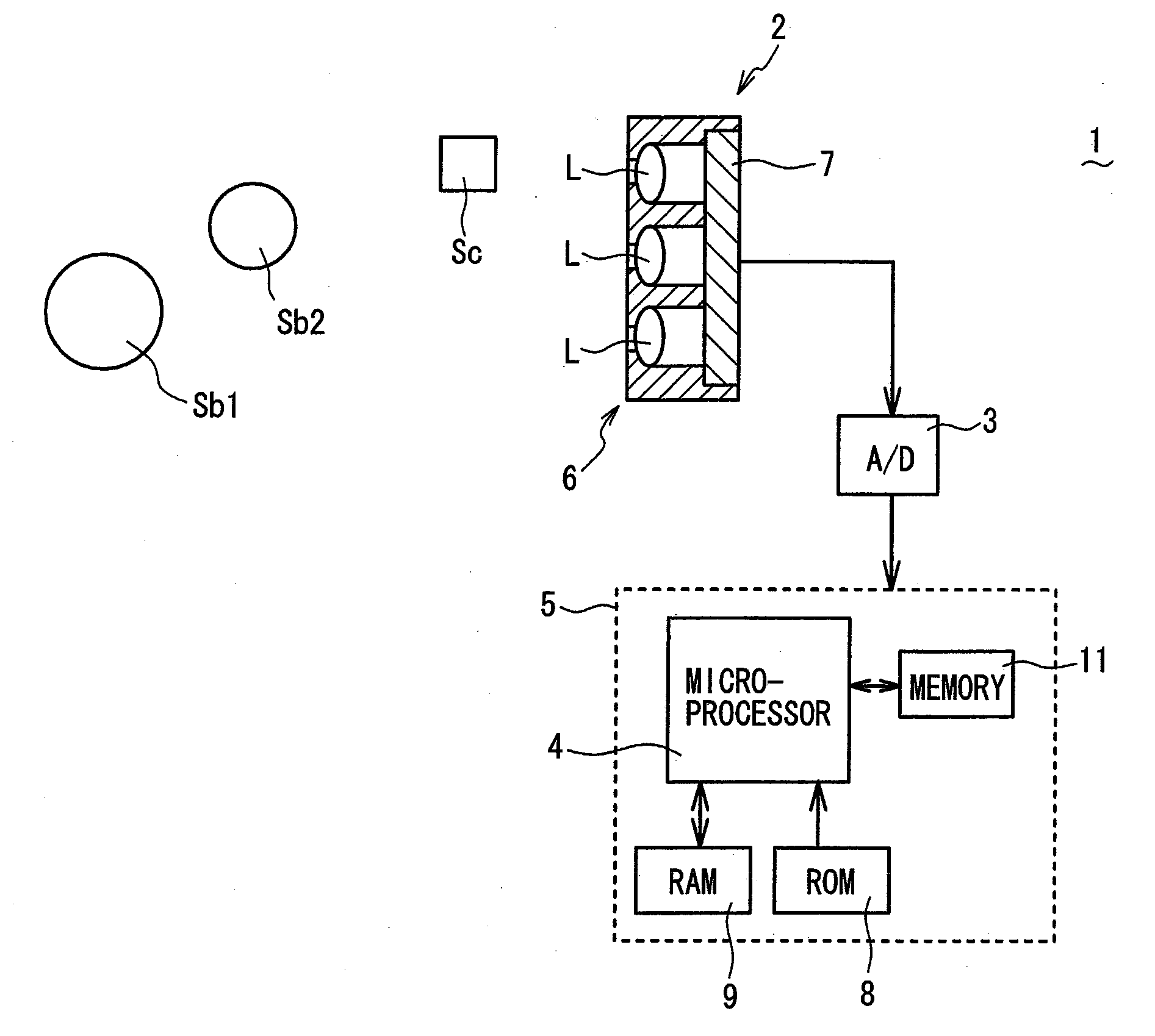
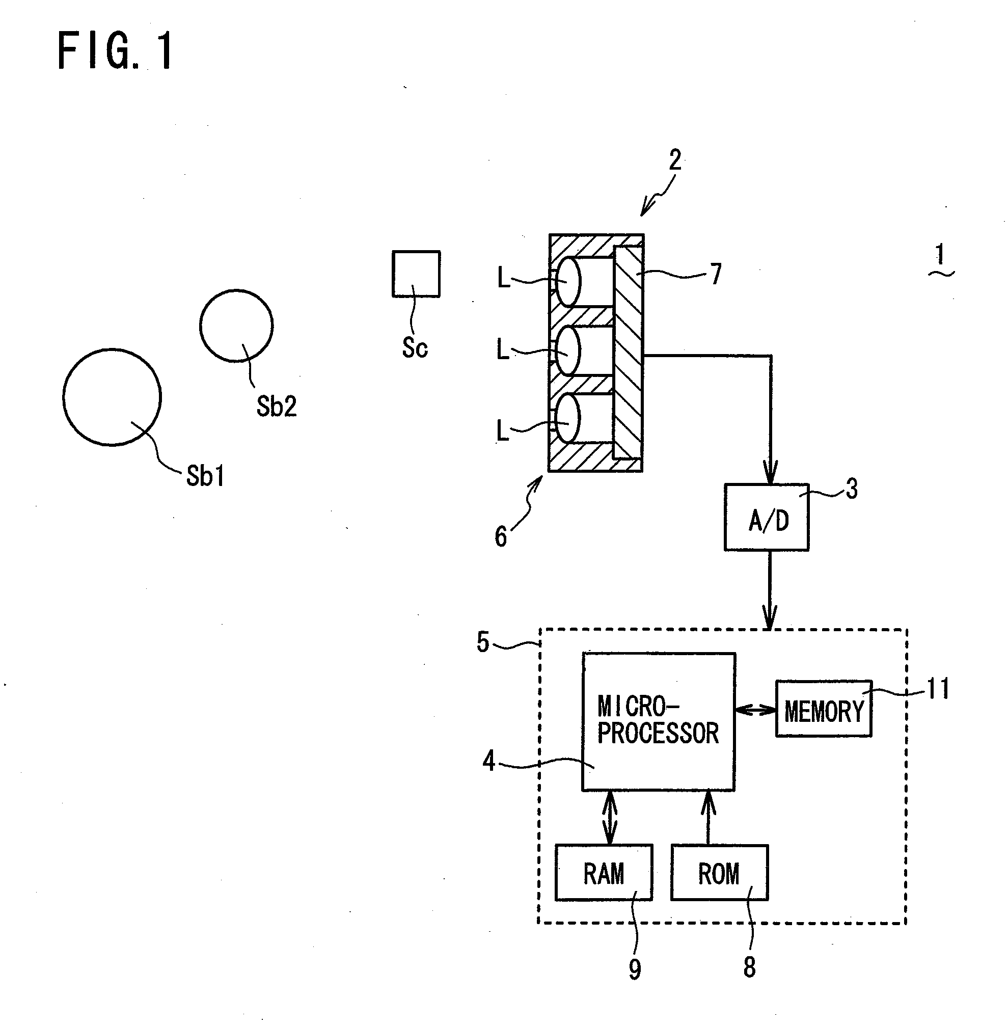
[0033]Referring to FIG. 1 to FIG. 11, an object distance deriving device 1 according to a first embodiment of the present invention will be described. FIG. 1 is a schematic view, partly in block form, of an object distance deriving device 1 of the present embodiment. As shown in FIG. 1, the object distance deriving device 1 comprises a compound-eye imaging unit 2 (claimed “imaging means”) and a distance calculation unit 5 (claimed “distance calculating means”) mainly composed of a microprocessor 4 for receiving, via an A / D (Analog-to-Digital) converter 3, image information captured by the compound-eye imaging unit 2, and for calculating a distance (object distance) between an object and the compound-eye imaging unit 2 (more specifically optical lens array 6) based on the received and digitized image information. As will be apparent from the description below, the microprocessor 4 serves as claimed “distance calculating means”, “distance setting means”, “reconstructed...

Example

Second Embodiment

[0054]An object distance deriving device 1 according to a second embodiment of the present invention is substantially the same as that of the first embodiment, except that in the second embodiment, the evaluation values SSD(x,y) as calculated in the evaluation value calculation step S4 in the flow chart of FIG. 3 are smoothed. More specifically, the microprocessor 4 applies a known smoothing filter to, and thereby smooths, the evaluation values SSD(x,y) as calculated in S4. By smoothing the calculation evaluation values SSD(x,y), the distribution of the evaluation values SSD(x,y) (smoothed evaluation values) on the XY plane becomes smooth (refer to FIG. 8), making it possible to more accurately derive the object distance by preventing an erroneous derivation of the object distance D due to determination of an improper temporary distance Di as the object distance D in the distance determining step S6. It is to be noted that the smoothing of the evaluation values SSD(...

Example

Third Embodiment

[0055]An object distance deriving device 1 according to a third embodiment of the present invention is substantially the same as that of the first embodiment except for the following two points. The first point is that according to the third embodiment, in the reconstructed image creating step S2 in the flow chart of FIG. 3, the microprocessor 4 extracts a high-frequency component of each of unit images k1 to k9 so as to create each corresponding high-frequency component unit image, and then creates one high-frequency component reconstructed image Adi from the nine high-frequency component unit images by using the same method as described above. The second point is that according to the third embodiment, in the reverse projection image creating step S3, the microprocessor 4 extracts a high-frequency component of each of unit images k1 to k9 so as to create each corresponding high-frequency component unit image, and then creates nine high-frequency component reverse p...


PUM


Abstract

An object distance deriving device comprises a compound-eye imaging unit for capturing n unit images and a microprocessor for calculating an object distance of an object from the imaging unit based on the unit images. The microprocessor sets a first temporary distance D1 from discrete temporary distances D1-Dn prepared in advance, and rearranges pixels of each unit image at D1 to create one reconstructed image. The microprocessor reversely projects the pixels of each unit image at D1 to create n reverse projection images. The microprocessor calculates and sums n deviations each between a pixel of the reconstructed image and that of each reverse projection image at each xy coordinate position to calculate an evaluation value for D1. The microprocessor repeats this process for the temporary distances D2-Dn to obtain n evaluation values. The microprocessor determines one of the temporary distances D1-Dn giving a minimum evaluation value as the object distance.

Description

BACKGROUND OF THE INVENTION[0001]1. Field of the Invention[0002]The present invention relates to an object distance deriving device, and more particularly to an object distance deriving device which uses imaging means and derives a distance of an object from the imaging means based on images captured by the imaging means.[0003]2. Description of the Related Art[0004]An image reconstruction device is known which reconstructs a single two-dimensional image by digital image processing of multiple unit images of a three-dimensional object as captured by a compound-eye camera having multiple microlenses (refer, for example, to Japanese Laid-open Patent Publication 2005-167484). The compound-eye camera has an advantage that it can be manufactured to be thin, and also can obtain a bright image easily. However, at the same time it has a disadvantage that the definition (resolution) of each captured unit image is low. In order to increase the definition of the images in the image processing t...

Claims


Application Information

Patent Timeline
IPC IPC(8): G06K9/00
CPCG06T3/00H04N25/41
Inventor TANIDA, JUNTOYODA, TAKASHINAKAO, YOSHIZUMIMASAKI, YASUO
Owner FUNAI ELECTRIC CO LTD
Why Eureka
Try Eureka