Method and system for enabling diagnosing of faults in a passive optical network

a passive optical network and fault diagnosis technology, applied in the field of passive optical network fault diagnosis, can solve the problems of ems having a limit to the number of alarms, unable to monitor stability of the ont and diagnose a source of instability, and becoming less feasible to rely on the management system to handle a large number of alarms

Inactive Publication Date: 2009-03-05
TELLABS VIENNA
View PDF2 Cites 49 Cited by
  • Summary
  • Abstract
  • Description
  • Claims
  • Application Information

AI Technical Summary

Problems solved by technology

It has always been very difficult to monitor stability of the ONT and diagnose a source of instability in part because of inherent characteristics of signaling paths within a PON.
However, when dealing with a large number of ONTs for a long duration of time, it becomes less feasible to rely on the management system to handle a large number of alarm conditions and diagnose causes of the alarm conditions.
Also, the EMS has a limit to the number of alarms it can store, and alarms beyond the limit are lost or overwrite previously stored alarms.
Thus, diagnosing faults in a passive optical network is challenging.

Method used


Image

  • Method and system for enabling diagnosing of faults in a passive optical network
  • Method and system for enabling diagnosing of faults in a passive optical network
  • Method and system for enabling diagnosing of faults in a passive optical network

Examples


Embodiment Construction

[0025]A description of example embodiments of the invention follows.

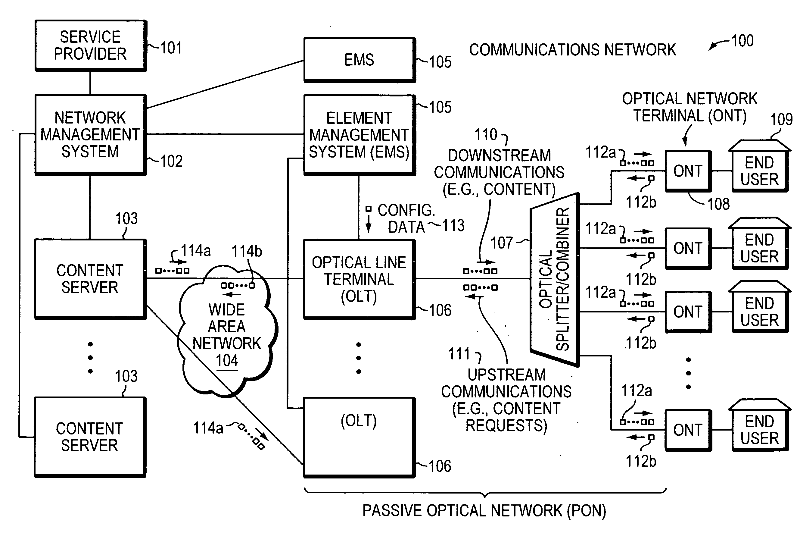
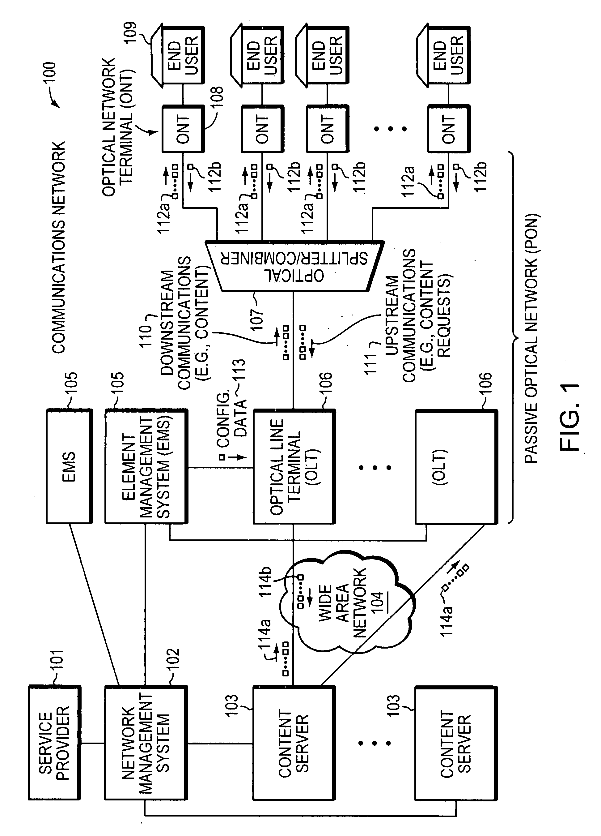
[0026]An example embodiment of the invention enables diagnosing of faults in a passive optical network (PON). Diagnosis can be difficult due to alarm message storage constraints in large networks and alarm and state information clearing or changing at nodes generating alarm messages after a change in alarm or other state by the nodes generating the alarm messages or by associated nodes. Centralized techniques for maintaining or diagnosing the alarm conditions are thus limited or ineffective. Therefore, a distributed approach based on information related to ranging of optical network terminals (ONTs) within the PON is employed in an example embodiment of the invention. The information related to ranging used by the example embodiment serves to overcome problems previously encountered in diagnosing faults in a PON, as described above. Before presenting details of example embodiments of the invention a description of a...


PUM


Abstract

In a passive optical network (PON), multiple optical network terminals (ONTS) transmit data to an optical line terminal (OLT) using a common optical wavelength and fiber optical media. Various components of the PON, including the OLT and ONT(s), can malfunction. Centralized techniques for maintaining or diagnosing fault conditions may be ineffective in large networks or in relatively small networks because of vast amounts of information and limited storage capacity for the information. Thus, fault conditions may occur and not be diagnosed due to lost or overwritten information. Therefore, a distributed approach based on information related to ranging of ONTs within the PON is employed in an example embodiment of the invention. This distributed approach can improve monitoring and diagnosis of fault conditions that may lead to instability of the PON.

Description

BACKGROUND OF THE INVENTION[0001]In a passive optical network (PON), multiple optical network terminals (ONTS) transmit data to an optical line terminal (OLT) using a common optical wavelength and fiber optic media. Various components of the PON, including the OLT and ONT(s), can malfunction. It has always been very difficult to monitor stability of the ONT and diagnose a source of instability in part because of inherent characteristics of signaling paths within a PON.[0002]In an event of an alarm condition on the ONT, the ONT may transmit a message autonomously to the OLT, which, in turn, may transmit a message to report the alarm condition to a management system. However, when dealing with a large number of ONTs for a long duration of time, it becomes less feasible to rely on the management system to handle a large number of alarm conditions and diagnose causes of the alarm conditions.[0003]Some information generated or learned by the ONTs cannot be retrieved from ONTs in certain ...

Claims


Application Information

Patent Timeline
Patent Type & Authority Applications(United States)
IPC IPC(8): H04B10/08
CPCH04J3/0682H04J3/1694H04Q2011/0081H04L41/0681H04Q11/0067H04L41/064
Inventor LIU, DAVID H.VENKATARAMAN, SREERAMRANDALL, PETER L.
Owner TELLABS VIENNA
Why Eureka
Try Eureka