Lubricant applicator, process cartridge including same, and image forming apparatus including same

a technology of lubricant applicator and process cartridge, which is applied in the direction of electrographic process apparatus, instruments, optics, etc., can solve the problems of reducing the efficiency of applying lubricant to the photoconductor, affecting the production of defective images, and difficult to estimate the location or adhesion of residual lubricating powder

Inactive Publication Date: 2009-03-05
RICOH KK
View PDF18 Cites 30 Cited by
  • Summary
  • Abstract
  • Description
  • Claims
  • Application Information

AI Technical Summary

Benefits of technology

[0031]In the above-described cleaning unit, the image carrier may be rotated by a drive motor in a given direction during a printing operation. The drive motor may cause the image carrier to rotate less than one

Problems solved by technology

The scattered lubricating powder can cause a reduction of efficiency for applying the lubricant to the photoconductor.
It is, however, difficult to estimate where the residual lubricating powder lands or adheres when scattered from the fur brush roller.
This random scattering of lubricating powder can contaminate the interior of the lubricant applicator, resulting in the production of defective imag

Method used


Image

  • Lubricant applicator, process cartridge including same, and image forming apparatus including same
  • Lubricant applicator, process cartridge including same, and image forming apparatus including same
  • Lubricant applicator, process cartridge including same, and image forming apparatus including same

Examples


first exemplary embodiment

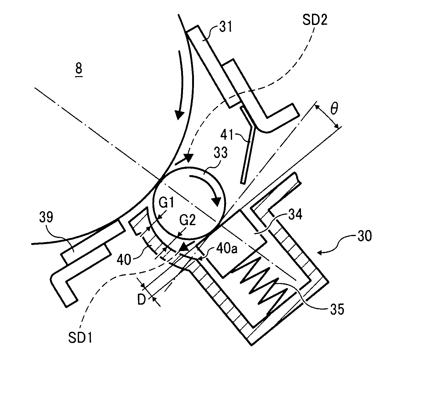
[0086]FIG. 4 shows a schematic configuration of a lubricant applicator 30 according to the first exemplary embodiment.

[0087]The lubricant applicator 30 includes the fur brush 33, the solid lubricant 34, the solid lubricant pressing spring 35, and a first guide member 40.

[0088]The first guide member 40 is provided between the application blade 39 and the fur brush 33 to effectively convey the lubricant scraped from the solid lubricant 34 to the surface of the photoconductor 8.

[0089]The fur brush 33 rotates in the direction of rotation of the photoconductor 8, and the elastic application blade 39 is held in contact with the surface of the photoconductor 8 in a counter manner or against the surface of the photoconductor 8. When compared with a blade arranged in a trailing manner, the elastic application blade 39 that is arranged in the counter manner with respect to the rotation of the photoconductor 8 can set a contact pressure to a low level, which can prevent or reduce loss of resil...

second exemplary embodiment

[0103]FIG. 5 illustrates a schematic structure of a lubricant applicator 30A according to a second exemplary embodiment of the present invention.

[0104]Elements or components of the lubricant applicator 30A of FIG. 5 may be denoted by the same reference numerals as those of the lubricant applicator 30 of FIG. 4 according to the first exemplary embodiment and the descriptions thereof are omitted or summarized.

[0105]A first guide member40A includes a curved portion 40c that is circular-arc-shaped in a cross section thereof and is concentric with the fur brush 33. The first guide member 40A has an inner surface facing the fur brush 33 and a gap therebetween is 1 mm or smaller.

[0106]However, the first guide member 40A may not necessarily be concentric with the fur brush 33. When the first guide member 40A is not concentric with the fur brush 33, the minimum distance of the gap between the fur brush 33 and the first guide member 40A preferably ranges 1 mm or smaller. With this gap, the lu...

third exemplary embodiment

[0112]FIG. 6 illustrates a schematic structure of a lubricant applicator 30B according to a third exemplary embodiment of the present invention.

[0113]Elements or components of the lubricant applicator 30B of FIG. 6 according to the third exemplary embodiment may be denoted by the same reference numerals as those of the lubricant applicator 30 of FIG. 4 according to the first exemplary embodiment and the descriptions thereof are omitted or summarized.

[0114]The lubricant applicator 30B includes a first guide member 40B that is U-shaped in its cross section and includes a metal plated member to hold the elastic application blade 39. By holding the elastic application blade 39 with the first guide member 40B as shown in FIG. 6, a shape of a frame to attach the first guide member 40B can be simpler.

[0115]Further, the one end of the first guide member 40 can be arranged closer to the point of contact between of the elastic application blade 39 and the photoconductor 8. Therefore, the lubr...


PUM


Abstract

A lubricant applicator, which is included in a process cartridge, and an image forming apparatus, includes a fur brush disposed downstream from a cleaning member in a direction of rotation of the image carrier that moves in the direction of rotation of the image carrier, scrape a solid lubricant disposed opposite to the image carrier while rotating, and apply powder scraped from the solid lubricant to the surface of the image carrier; a lubricant fixing member to fix the powder to the surface of the image carrier; and a first guide member disposed between the lubricant fixing member and the fur brush to convey the powder scattered from the fur brush to the surface of the image carrier.

Description

CROSS-REFERENCE TO RELATED APPLICATIONS[0001]The present invention claims priority pursuant to 35 U.S.C. §119 from Japanese Patent Application Nos. 2007-228729, filed on Sep. 4, 2007 in the Japan Patent Office; 2007-305555, filed on Nov. 27, 2007 in the Japan Patent Office; and 2008-116872, filed on Apr. 28, 2008 in the Japan Patent Office, the contents and disclosures of each of which are hereby incorporated by reference herein in their entirety.BACKGROUND OF THE INVENTION[0002]1. Field of the Invention[0003]Exemplary embodiments of the present invention generally relate to a lubricant applicator, a process cartridge, and an image forming apparatus, and more particularly, to a lubricant applicator that performs electrophotographic image forming processes, a process cartridge that includes the lubricant applicator, and an image forming apparatus that includes the lubricant applicator.[0004]2. Discussion of the Related Art[0005]Related-art electrophotographic image forming apparatuse...

Claims


Application Information

Patent Timeline
IPC IPC(8): G03G21/00
CPCG03G21/00G03G15/75
Inventor NINOMIYA, HIROMICHITAWADA, TAKAAKIFUJISHIRO, TAKATSUGUFUJIMORI, AKIRA
Owner RICOH KK
Why Eureka
Try Eureka