Ventilation arrangement

a technology of ventilation arrangement and valve body, which is applied in the direction of liquid fuel engine, marine propulsion, vessel construction, etc., can solve the problems of overheating problems of these components, electronic circuits or batteries may malfunction at excess temperatures, and only guarantee the reliable operation of several components

Active Publication Date: 2009-03-05
GENERAL ELECTRIC CO
View PDF9 Cites 97 Cited by
  • Summary
  • Abstract
  • Description
  • Claims
  • Application Information

AI Technical Summary

Problems solved by technology

However, reliable operation of several components is only guaranteed within a certain temperature range.
For example, electronic circuits or batteries may malfunction at excess temperatures.
Due to the several heat sources inside the hub, overheating problems of these components may occur, especially during summer.
However, these ventilation holes are relatively small since, otherwise, water may leak into the interior of the hub through the ventilation holes.
Of course, this is unfavorable in view of the sensitive electrical and mechanical installations in the hub.
Therefore, only a small amount of heat can be exchanged through the small ventilation holes but the cross-sectional area of the ventilation holes cannot be simply enlarged.

Method used


Image

  • Ventilation arrangement
  • Ventilation arrangement
  • Ventilation arrangement

Examples


Embodiment Construction

[0017]Reference will now be made in detail to the various embodiments of the invention, one or more examples of which are illustrated in the figures. Each example is provided by way of explanation of the invention, and is not meant as a limitation of the invention. For example, features illustrated or described as part of one embodiment can be used on or in conjunction with other embodiments to yield yet a further embodiment. It is intended that the present invention includes such modifications and variations. Furthermore, like reference numerals designate like features in the embodiments.

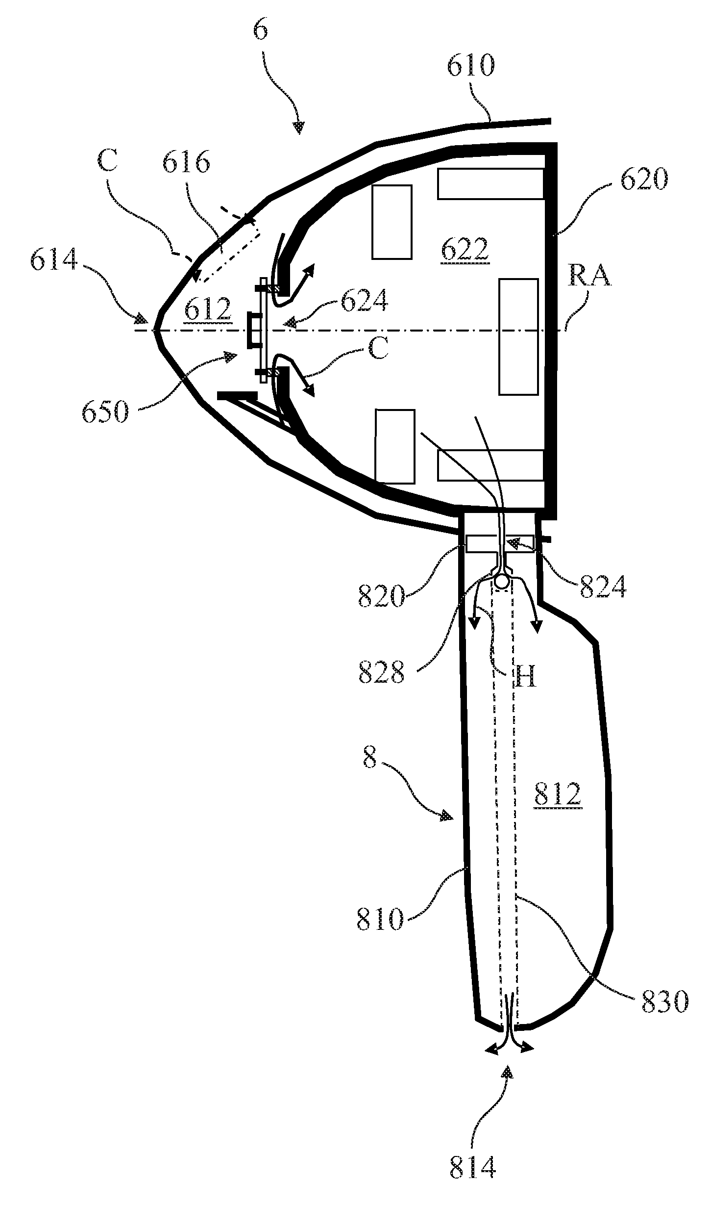
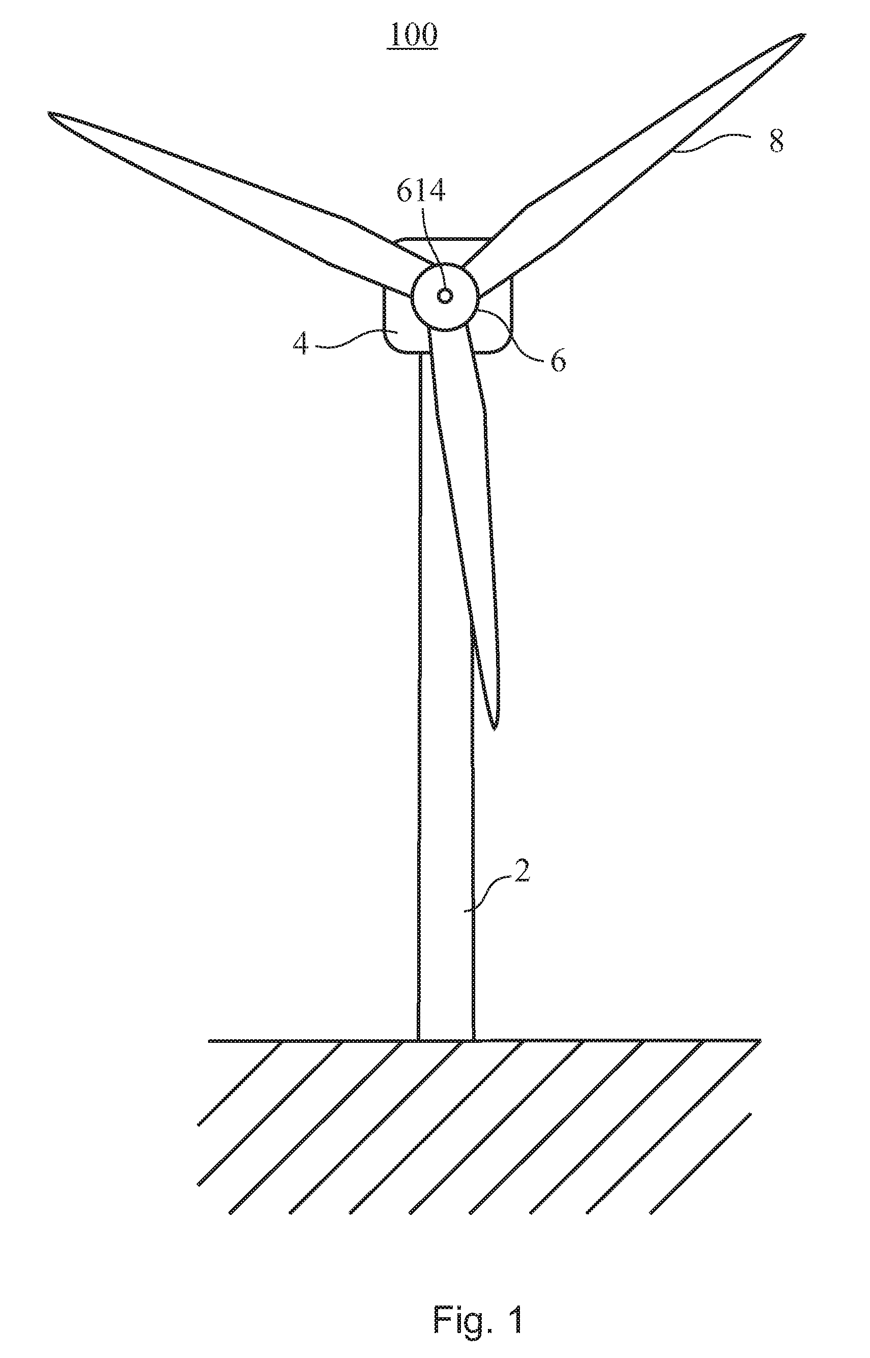
[0018]FIG. 1 shows a front view of a wind turbine 100 according to an embodiment of the present invention. The wind turbine includes a tower 2 which has a machine nacelle 4 mounted to its top end. A rotor hub 6 is attached to one end of nacelle 4 so that it can it can rotate about an axis essentially parallel to the ground. In the embodiment shown, three rotor blades 8 are attached to rotor hub 6. ...


PUM


Abstract

A ventilation arrangement for a wind turbine includes an air inlet opening located in a nose cone of said wind turbine, a manhole cover for covering a manhole of a rotor hub of said wind turbine, the manhole cover providing a vent opening for venting hot air from an internal space of said rotor hub, and a flexible piping establishing fluid communication between the internal space of the rotor hub and the air inlet opening.

Description

BACKGROUND OF THE INVENTION[0001]The present invention relates to a ventilation arrangement for a wind turbine rotor hub, and a manhole cover which may be applied in such ventilation arrangement.[0002]Many installations inside the hub of a wind turbine rotor produce heat during operation. In particular, heat sources inside the hub are as diverse as relays installed in switch cabinets, batteries, chargers for batteries, pitch drive motors, pitch gear boxes, and pitch drive controllers, hydraulic units, as well as the main shaft bearing in some designs. However, reliable operation of several components is only guaranteed within a certain temperature range. For example, electronic circuits or batteries may malfunction at excess temperatures. Due to the several heat sources inside the hub, overheating problems of these components may occur, especially during summer.[0003]To solve these overheating problems, ventilation holes are provided in the hub of some wind turbine designs. However,...

Claims


Application Information

Patent Timeline
Patent Type & Authority Applications(United States)
IPC IPC(8): F03D11/00
CPCF03D11/00F05B2260/20Y02E10/722F05B2260/64Y02E10/721F05B2260/602F03D80/60Y02E10/72
Inventor LANDA, BERNARD P.POTER, LANEUPHUES, ULRICHWILLEY, LAWRENCE D.NEUMANN, ULRICHMARTIN, NEGEL E.
Owner GENERAL ELECTRIC CO
Why Eureka
Try Eureka