Sealing stopper and assembly comprising such a sealing stopper

Inactive Publication Date: 2009-03-05
GYNAECOLOGIQ
View PDF8 Cites 2 Cited by
  • Summary
  • Abstract
  • Description
  • Claims
  • Application Information

AI Technical Summary

Benefits of technology

[0010]It is an object of the present invention to achiev

Problems solved by technology

With the device according to U.S. Pat. No. 5,248,304, it is not readily possib

Method used


Image

  • Sealing stopper and assembly comprising such a sealing stopper
  • Sealing stopper and assembly comprising such a sealing stopper
  • Sealing stopper and assembly comprising such a sealing stopper

Examples


Embodiment Construction

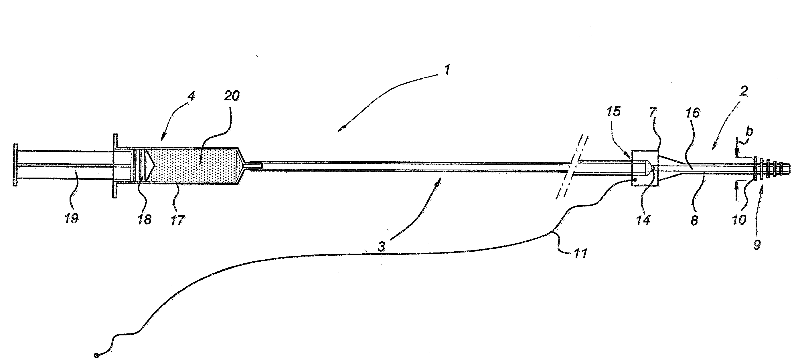
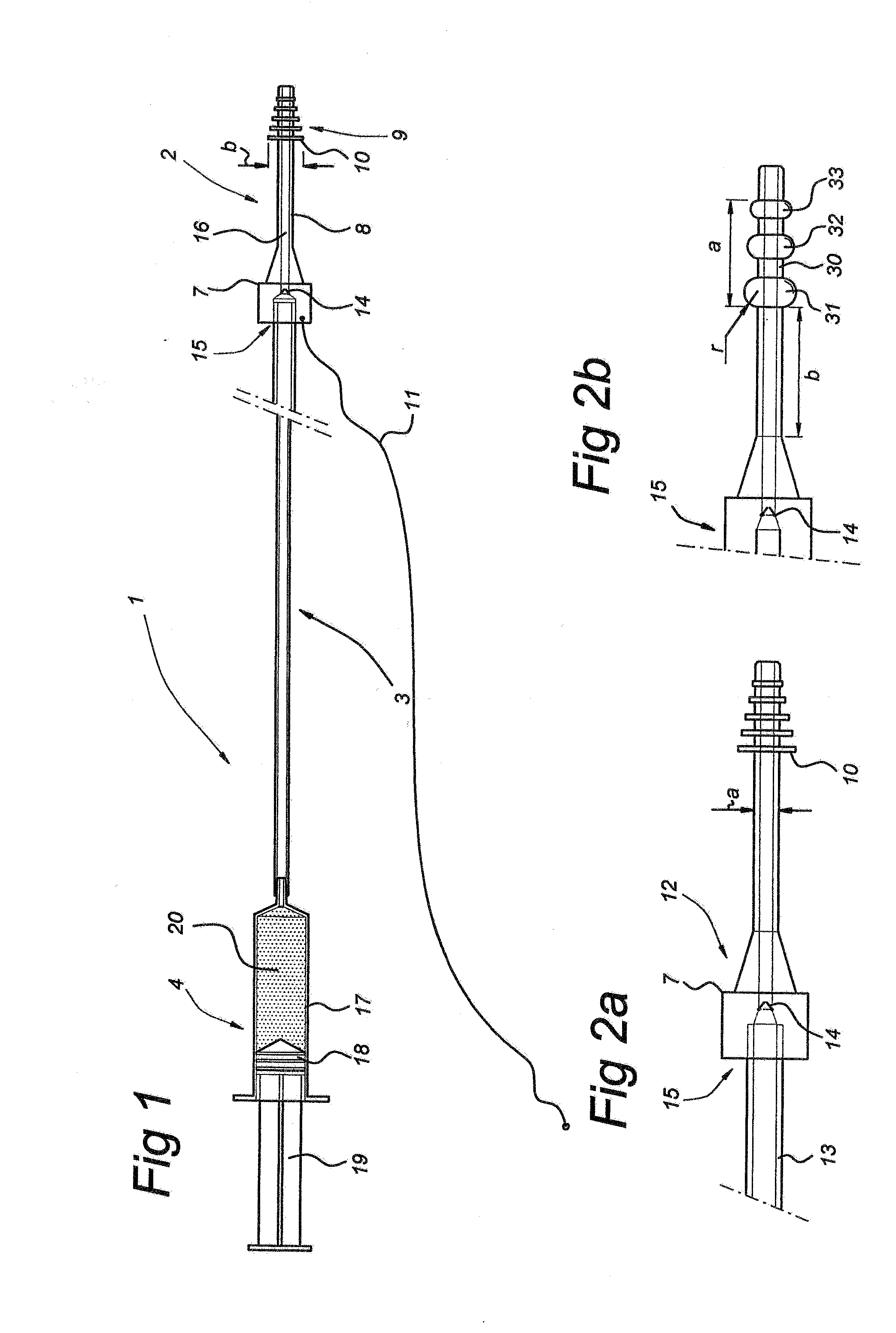
[0030]In FIG. 1, the assembly according to the present invention is denoted overall by reference numeral 1. It consists of a sealing stopper 2, a connecting hose 3 connected there to, and a syringe 4. The connecting hose 3 is accommodated in the socket 15 of a thickened part 7 of the sealing stopper 2 in a slightly clamping manner. This thickened part 7 simultaneously serves as a stop. A tube 8 is connected to the latter. A liquid supply duct 16 extends through the entire assembly. Reference numeral 14 denotes a non-return valve. Near its free end, the tube 8 is provided with flexible ribs 10. The tube 8 and ribs 10 form the parts to be introduced and are denoted by reference numeral 9. The external diameter b of the flexible ribs 10 is preferably less than 15 mm.

[0031]Connecting hose 3 can be coupled to a syringe-type structure 4 which consists of a piston 18 connected to a handle 19 which piston is guided in a cylinder 17 containing gel 20.

[0032]Stop 7 is connected to a piece of s...


PUM


Abstract

In order to enlarge the uterus, inter alia for diagnostic purposes, it is proposed to seal the cervix once a liquid, such as a gel, has been introduced, by means of a sealing stopper, so that liquid does not constantly have to be supplied to the uterus. The sealing stopper is preferably coupled to a gel feed device which may comprise a simple syringe-type structure. This system comprises a non-return valve, as a result of which a gel can only be displaced in the direction of the uterus. In order to ensure that the sealing stopper can be removed, return means, such as a piece of string, are attached thereto.

Description

BACKGROUND OF THE INVENTION[0001]In conducting diagnostic treatments such as echoscopy, it is usual that the uterus is enlarged by introducing a watery liquid. This is carried out with a hose which is arranged in the cervix. The hose is fitted with a stopper which abuts the external ostium. During echoscopy the flow of water is constantly monitored and at the location of the stopper water constantly escapes from the hose while the water is being introduced via the hose and by accurately controlling the amount of water supplied, the enlargement of the uterus can be controlled.[0002]Such an enlargement method is uncomfortable for the individual being examined and inconvenient for the treating physician. After all, the uterus has to be monitored constantly in order to ensure that the enlargement remains unchanged. With echoscopy in particular, it is important that no changes occur since the images obtained by this method otherwise do not allow unambiguous diagnosis or treatment.[0003]I...

Claims


Application Information

Patent Timeline
IPC IPC(8): A61M39/02A61M39/22
CPCA61M31/00
Inventor EXALTO, NIEKEMANUEL, MARK HANS
Owner GYNAECOLOGIQ
Why Eureka
Try Eureka