Barbed stent vascular occlusion device

a vascular occlusion device and barbed stent technology, applied in the field of vascular occlusion devices, can solve the problems of patient open to a risk of injury, take a significant period of time for sufficient tissue to grow to fully occlude the body cavity, and balloons have the disadvantage of being temporary, so as to promote body tissue growth

Inactive Publication Date: 2009-03-05
COOK INC
View PDF58 Cites 39 Cited by
  • Summary
  • Abstract
  • Description
  • Claims
  • Application Information

AI Technical Summary

Benefits of technology

[0006]In satisfying the above need, as well as overcoming the enumerated drawbacks and other limitations of the related art, the present invention provides a vascular occlusion device for occluding a body cavity. The device includes a tubular scaffold extending from a proximal end to a distal end. The scaffold is formed from a plurality of interconnected and articulated members configured to self-expand into an open configuration. A plurality of barbs extend from the articulated members to an anchoring end. The anchoring end is disposed radially outward from the scaffold in the open configuration and adapted to embed into the cavity walls. A radially expandable substance is disposed within a device lumen. The substance is configured to promote body tissue growth from body cavity walls to occlude the body cavity. In some examples, the anchoring ends of the barbs are disposed substantially flush along the scaffold in a closed configuration.

Problems solved by technology

However, balloon's have the disadvantage of being temporary.
It may take a significant period of time for sufficient tissue to grow to fully occlude the body cavity.
This leaves a patient open to a risk of injury from the condition which requires the body cavity be occluded.

Method used


Image

  • Barbed stent vascular occlusion device
  • Barbed stent vascular occlusion device
  • Barbed stent vascular occlusion device

Examples


Embodiment Construction

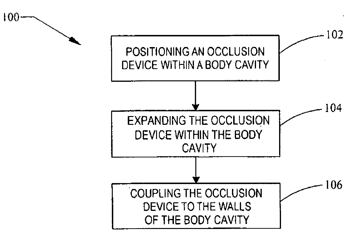
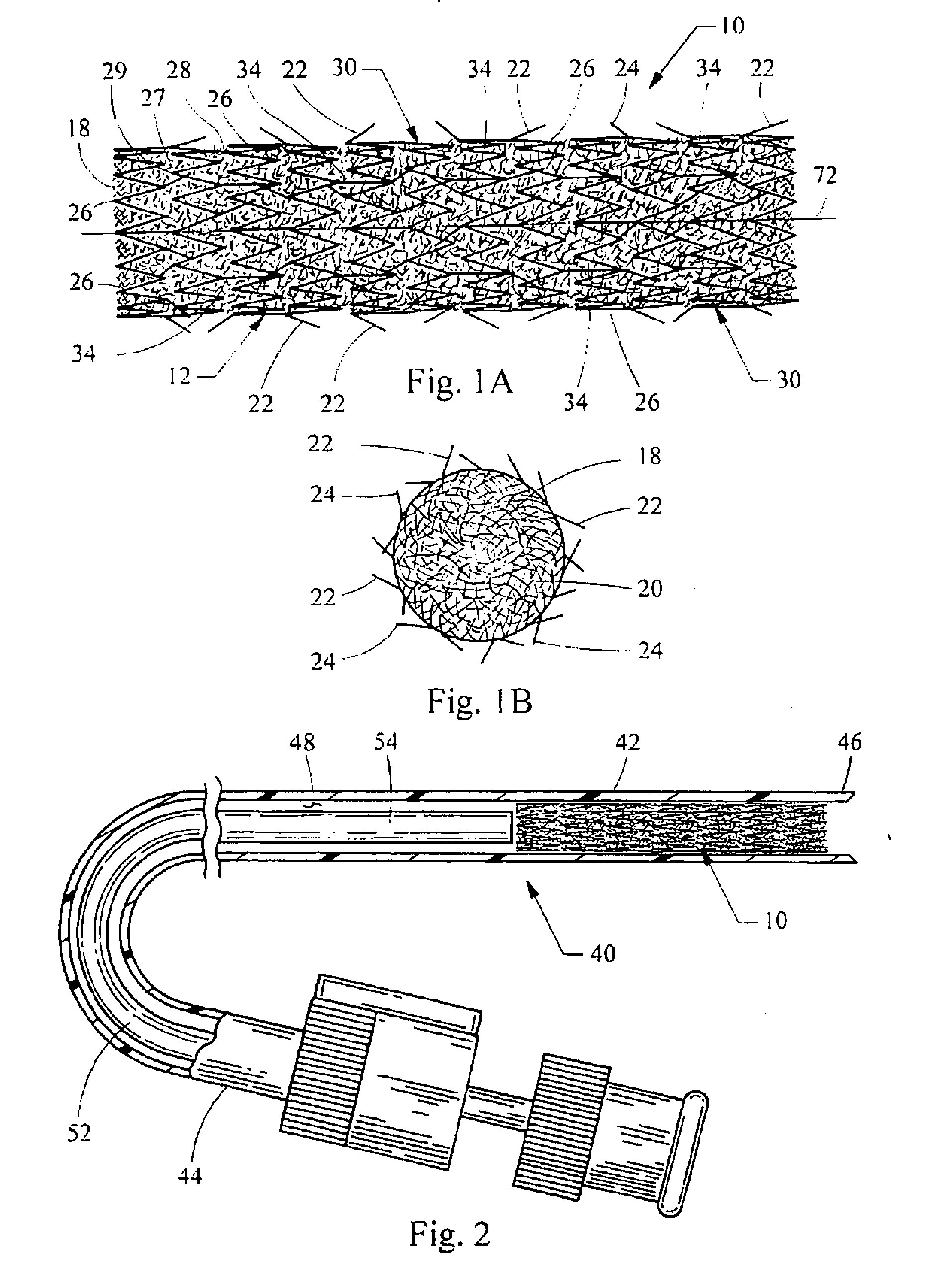
[0023]Referring now to FIGS. 1A and 1B, an occlusion device embodying the principles of the present invention is illustrated therein and designated at 10. As its primary components, the occlusion device 10 includes tubular scaffold 12 extending from a proximal end 14 to a distal end 16 and defining a device lumen 18 therethrough. A plurality of barbs 22 are attached to the scaffold 12, and a radially expandable substance 20 is at least partially disposed within the device lumen 18 and attached to the scaffold 12. The substance 20 is configured to promote tissue growth within a body cavity.

[0024]In one embodiment, the scaffold 12 is formed from a plurality of interconnected and articulated members 26 configured to expand into an open configuration as best shown in FIGS. 1A and 1B. Each of the articulated members 26 have a proximal tip 27 and a distal tip 28 with each of the proximal and distal tips 27 and 28 being attached at a joint 29 to a respective proximal or distal tip 27 or 28...


PUM


Abstract

A vascular occlusion device for occluding a body cavity. The device includes a tubular scaffold extending from a proximal end to a distal end. The scaffold is formed from a plurality of interconnected and articulated members configured to self-expand into an open configuration. A plurality of barbs extend from the articulated members, each barb including an anchoring end. The anchoring end is disposed radially outward from the scaffold in the open configuration and adapted to embed into the cavity walls. A radially expandable substance is disposed within a device lumen. The substance is configured to promote body tissue growth within the body cavity to occlude the body cavity. In one example, the body cavity includes a patent foramen ovale.

Description

BACKGROUND OF THE INVENTION[0001]1. Field of the Invention[0002]The present invention generally relates to vascular occlusion devices. More specifically, the invention relates to a vascular occlusion device for repairing an atrial septal defect.[0003]2. Description of Related Art[0004]A number of different devices may be used to occlude a body cavity including, for example, a blood vessel. When it is desirable to quickly occlude a blood vessel, an inflatable balloon may be used. However, balloon's have the disadvantage of being temporary. Another example of an occlusion device includes embolization coils. Embolization coils are permanent and promote blood clots or tissue growth over a period of time, thereby occluding the body cavity. However, while the blood clots or the tissue grows, blood may continue to flow past the coil and through the body cavity. It may take a significant period of time for sufficient tissue to grow to fully occlude the body cavity. This leaves a patient ope...

Claims


Application Information

Patent Timeline
Patent Type & Authority Applications(United States)
IPC IPC(8): A61M29/00
CPCA61B17/12022A61B17/12109A61B17/12172A61B17/12177A61B2017/00575A61B2017/00579A61M2025/0681A61B2017/00623A61F2/91A61F2/95A61F2002/8483A61M25/00A61B2017/00601
Inventor KURRUS, MICHAEL R.
Owner COOK INC
Why Eureka
Try Eureka