
Method for sootblowing optimization

a technology of optimization and soot blowing, which is applied in the direction of boiler cleaning control devices, solid removal, tableware washing/rinsing machines, etc., can solve the problems of reducing the efficiency of the boiler, reducing the heat transfer efficiency of the tubes, and reducing the boiler efficiency, so as to achieve the determination of the cleanliness levels of different heat zones in the boiler.

Inactive Publication Date: 2009-03-05
GE DIGITAL HLDG LLC
View PDF35 Cites 6 Cited by
  • Summary
  • Abstract
  • Description
  • Claims
  • Application Information

AI Technical Summary

Benefits of technology

"The present invention is about improving the efficiency of fossil fuel boilers by optimizing the removal of combustion deposits. The invention includes methods and systems for determining and effecting boiler cleanliness levels and the operating settings of sootblowers. One aspect of the invention involves using a system model of the boiler that relates cleanliness levels to its performance. The model predicts the performance of the boiler based on its current cleanliness conditions and boiler operating conditions. The invention also includes an indirect controller that uses the system model to adjust the boiler's cleanliness levels and sootblower's operating parameters to achieve the desired performance goals. The invention can be adaptive and can be retrained periodically or as needed to maintain its effectiveness over time. The invention allows for comprehensive and coordinated cleanliness levels for different heat zones in the boiler and can determine sootblower operating parameters in terms of the performance of the boiler. Overall, the invention improves the operating efficiency of fossil fuel boilers by optimizing the removal of combustion deposits."

Problems solved by technology

These deposits generally decrease the efficiency of the boiler, particularly by reducing heat transfer in the boiler.
When combustion deposits accumulate on the heat transfer tubes that transfer the energy from the combustion to water, creating steam, for example, the heat transfer efficiency of the tubes decreases, which in turn decreases the boiler efficiency.
Maintaining completely soot-free boilers is not practical under actual operating conditions because the cleaning itself is expensive and creates wear and tear on the boiler system.
Cleaning generally requires diverting energy generated in the boiler, which negatively impacts the efficiency of the boiler and makes the cleaning costly.
Injection of the cleaning medium into the boiler also reduces the efficiency of the boiler and prematurely damages heat transfer surfaces in the boiler, particularly if they are over-cleaned.
Boiler surfaces, including heat transfer tubes, can also be damaged as a result of erosion by high velocity air or steam jets and / or as a result of thermal impact from jets of a relatively cool cleaning medium, especially air or liquid, impinging onto the hot boiler surfaces, especially if they are relatively clean.
Boiler surface and water wall damage resulting from sootblowing is particularly costly because correction requires boiler shutdown, cessation of power production, and immediate attention that cannot wait for scheduled plant outages.
Accordingly, reasonable, but less than ideal, boiler cleanliness levels are typically maintained in the boiler.
The above-described system does not relate the boiler performance to the required level of heat surface cleanliness and, therefore, to the optimum operating parameters.
Not only can performance goals change, but selecting performance goals does not necessarily determine the efficiency set points for the sootblowers in the system.

Method used


Image

  • Method for sootblowing optimization
  • Method for sootblowing optimization
  • Method for sootblowing optimization

Examples


Embodiment Construction

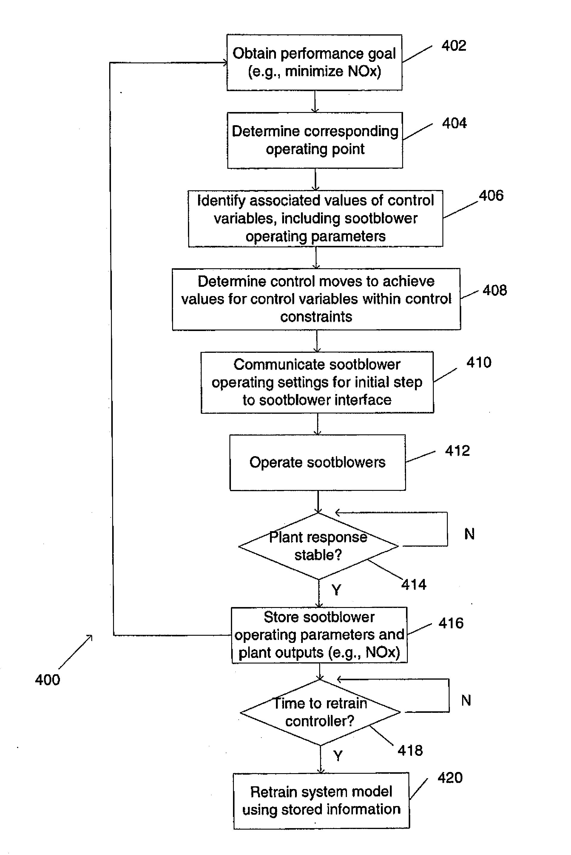
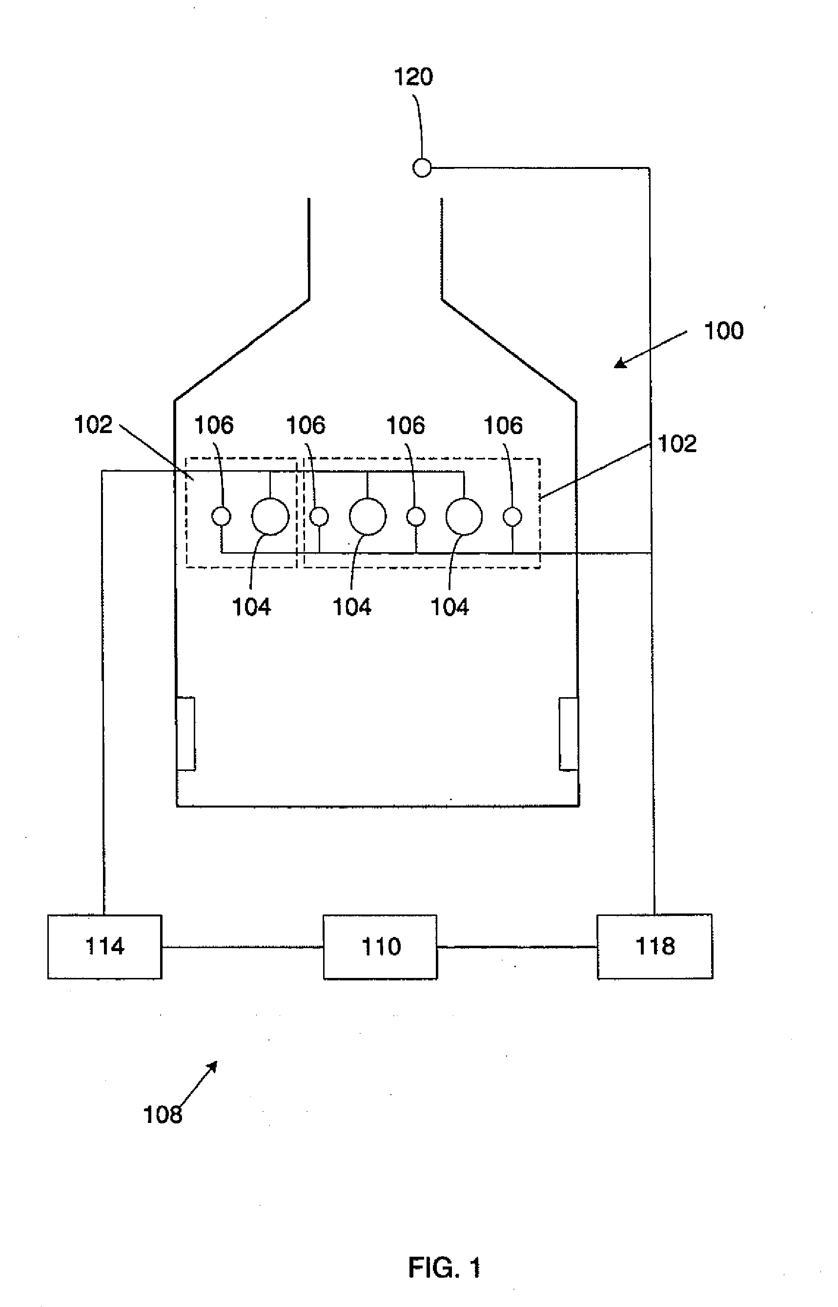
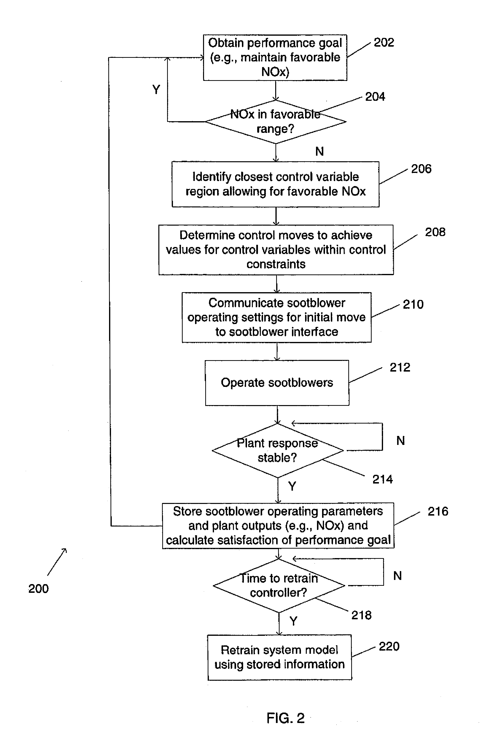
[0025]As illustrated in FIG. 1, in order to maintain boiler efficiency, a fossil fuel boiler 100 is divided into one or more heat zones 102, each of which can separately be monitored for heat transfer efficiency. In order to clean the boiler surfaces in a heat zone 102 when the heat transfer efficiency in the heat zone 102 degrades below a desired level due to the accumulation of soot, each heat zone 102 includes one or more sootblowers 104. Each heat zone 102 also includes one or more sensors 106 that measure one or more properties indicative of the amount of soot on the boiler surfaces in the heat zone 102. The data collected by the sensors 106 is useful both for timing sootblowing operations and for determining the effectiveness of sootblowing operations. The boiler 100 includes a deposit removal optimization system 108, with a controller 110 that configures a sootblower control interface 114 in communication with sootblowers 104. The deposit removal optimization system 108 adjus...


PUM


Abstract

A controller determines and adjusts system parameters, including cleanliness levels or sootblower operating settings, that are useful for maintaining the cleanliness of a fossil fuel boiler at an efficient level, Some embodiments use a direct controller to determine cleanliness levels and / or sootblower operating settings. Some embodiments use an indirect controller, with a system model, to determine cleanliness levels and / or sootblower settings. The controller may use a model that is, for example, a neural network, or a mass energy balance, or a genetically programmed model. The controller uses input about the actual performance or state of the boiler for adaptation. The controller may operate in conjunction with a sootblower optimization system that controls the actual settings of the sootblowers. The controller may coordinate cleanliness settings for multiple sootblowers and / or across a plurality of heat zones in the boiler.

Description

RELATED APPLICATIONS[0001]This application is a divisional of U.S. application Ser. No. 10 / 841,592, filed May 7, 2004, which is a continuation of U.S. application Ser. No. 10 / 455,598, filed Jun. 5, 2003. The aforementioned patent applications are fully incorporated herein by reference.FIELD OF THE INVENTION[0002]The invention relates generally to increasing the efficiency of fossil fuel boilers and specifically to optimizing sootblower operation in fossil fuel boilers.BACKGROUND OF THE INVENTION[0003]The combustion of coal and other fossil fuels during the production of steam or power produces combustion deposits, i.e., slag, ash and / or soot, that accumulate on the surfaces in the boiler. These deposits generally decrease the efficiency of the boiler, particularly by reducing heat transfer in the boiler. When combustion deposits accumulate on the heat transfer tubes that transfer the energy from the combustion to water, creating steam, for example, the heat transfer efficiency of th...

Claims


Application Information

Patent Timeline
Patent Type & Authority Applications(United States)
IPC IPC(8): G05B21/00F22B37/56F23J3/02F28G1/16
CPCF23J3/023Y10T436/12F22B37/56F28G1/16F28G15/003
Inventor LEFEBVRE, W. CURTKOHN, DANIEL W.
Owner GE DIGITAL HLDG LLC
Learn More