Lost wax investment casting gating fixtures

a technology of gating fixtures and lost wax, which is applied in the direction of manufacturing tools, foundry patterns, foundry moulding apparatus, etc., can solve the problems of difficult and time-consuming types of fixtures, process generates a significant amount of human error, and the use of wax or aluminum fixtures also has disadvantages

Inactive Publication Date: 2009-03-12
RAYTHEON TECH CORP
View PDF11 Cites 12 Cited by
  • Summary
  • Abstract
  • Description
  • Claims
  • Application Information

AI Technical Summary

Benefits of technology

[0006]A method of forming a gating fixture for a lost wax casting process includes determining a proper orientation of a gate in relation to a part, an

Problems solved by technology

This process generates a significant amount of human error, with each pattern being assembled differently from the next despite best efforts to provide consistent attachment points.
The use of wax

Method used


Image

  • Lost wax investment casting gating fixtures
  • Lost wax investment casting gating fixtures
  • Lost wax investment casting gating fixtures

Examples


Embodiment Construction

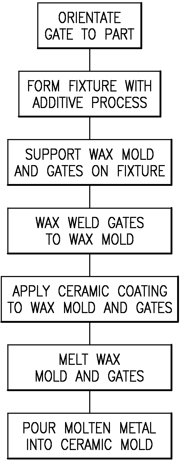
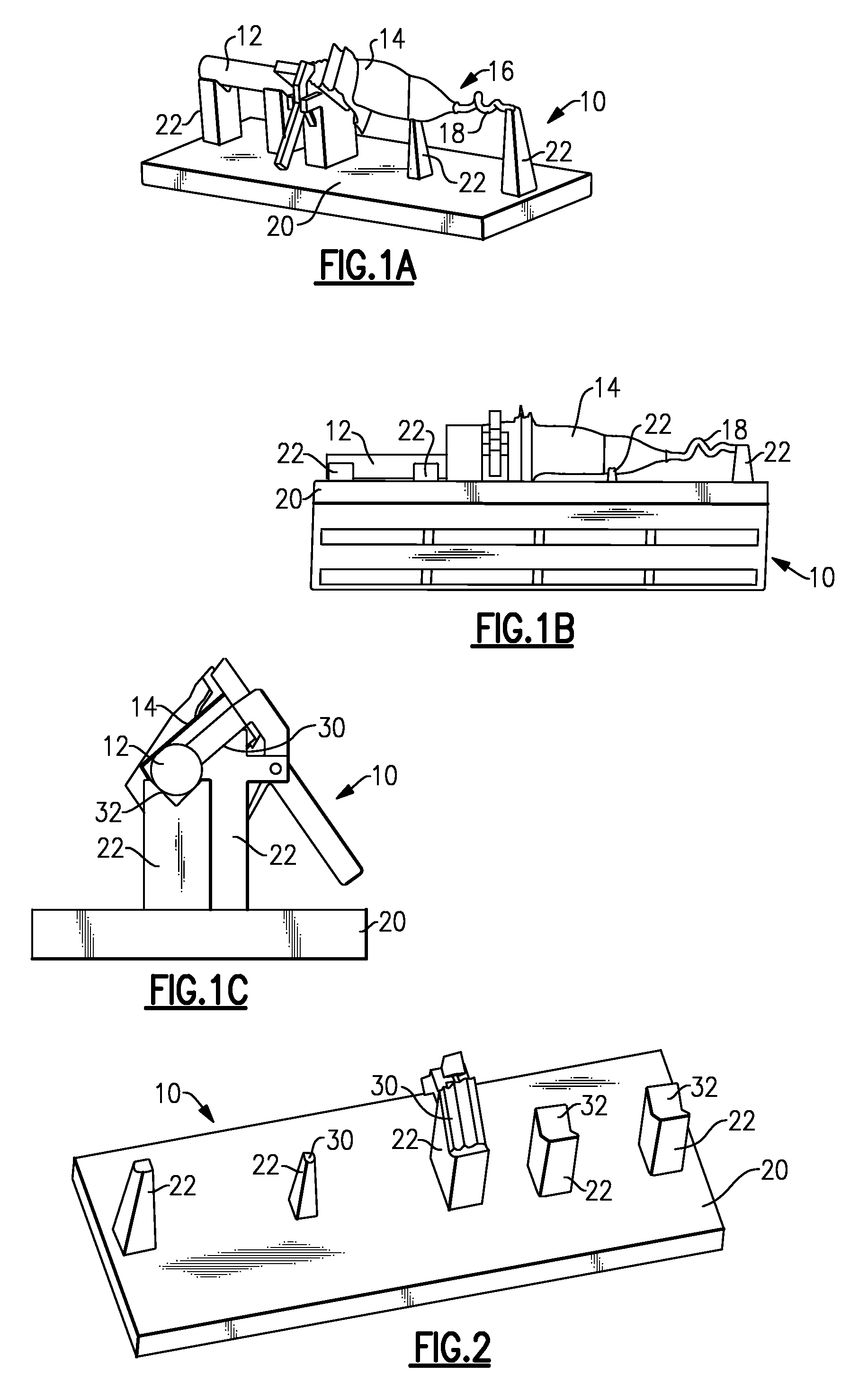
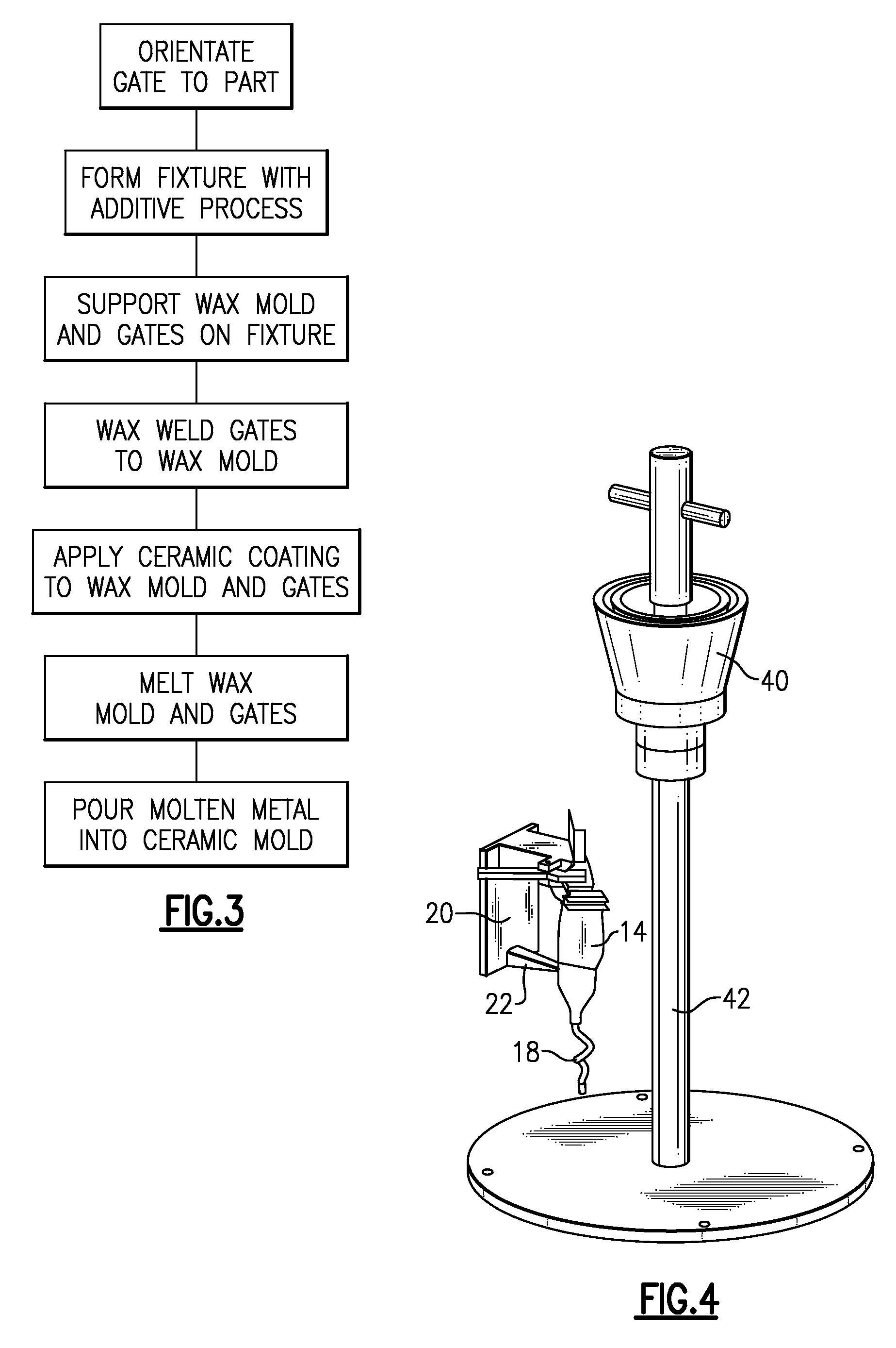
[0017]A fixture 10 for a lost wax investment casting process is shown in FIGS. 1A-1C. The fixture 10 is used to support one or more gates 12 in a desired orientation relative to a wax mold 14 of a part to be cast. The gates 12 define fluid flow paths for molten material that is used to form the part during casting.

[0018]When a part is to be made from a lost wax investment casting process, a fixture 10 is designed specifically for that part to ensure that gates 12 are set in a proper, i.e., optimal, orientation to the part to ensure adequate filling and proper grain growth during casting of the part.

[0019]The fixture 10 can also be used to support a single crystal seed 16 and a single crystal helix 18 that are associated with at least one of the gates 12. Single crystalline structure refers to a structure where all grain boundaries of the material are aligned with each other in a row. The helix 18 is used for orientation purposes to promote such a grain growth for the part during cas...


PUM


Abstract

A method of forming a gating fixture for a lost wax casting process includes determining an optimal orientation of a gate in relation to a part, and forming a fixture that can repeatably be used to consistently locate the gate relative to the part. In one example, stereolithography is used to form the fixture.

Description

TECHNICAL FIELD[0001]The subject invention relates to a gating fixture that is used in a lost wax investment casting process.BACKGROUND OF THE INVENTION[0002]In a lost wax investment casting process it is important to properly align a wax gate such that a ceramic shell can be adequately filled with molten metal. Proper alignment is also required to ensure proper grain growth as the molten metal cools.[0003]Traditionally, assemblers have manually attached wax gates to a part based on a sample photograph, or by using gating fixtures made from aluminum or wax. In the first situation, assemblers would look at the photograph and then use rulers and protractors to measure gate lengths and degree of orientation with respect to a wax pattern of the part. Wax gates would then be cut out and wax welded to the wax pattern based on the measurements. This process generates a significant amount of human error, with each pattern being assembled differently from the next despite best efforts to pro...

Claims


Application Information

Patent Timeline
IPC IPC(8): B22C7/02B22C9/00
CPCB22C7/02B22C21/14B22C9/04B33Y70/00
Inventor HASSELBERG, TIMOTHY P.KENNARD, LEA D.VERNER, CARL R.BULLIED, STEVEN J.BARTHOLOMEW, MARK F.
Owner RAYTHEON TECH CORP
Why Eureka
Try Eureka