Electric safety braking device with permanent magnet motor and breaking torque control

a technology of electric safety braking and permanent magnet motor, which is applied in the direction of motor/generator/converter stopper, dynamo-electric converter control, stopping arrangement, etc., can solve the problems of inability to adjust, the probability of failure must be extremely low, and the inability to secure the braking device, etc., to achieve efficient electric safety braking

Active Publication Date: 2009-03-12
ALSTOM TRANSPORT TECH SAS
View PDF7 Cites 13 Cited by
  • Summary
  • Abstract
  • Description
  • Claims
  • Application Information

AI Technical Summary

Benefits of technology

[0009]An object of the device proposed by this invention is to allow the force/speed characteristic of this electric safety brake to be adjusted in order to make

Problems solved by technology

However, it is not secure in the sense that it involves a large number of electric, electronic, mechanical, pneumatic or hydraulic components which may malfunction and therefore bring about a different braking force from that desired, or even, with the new traction chains having traction/static braking commutation, a traction force.
This brake cannot be adjusted but is reliable, that is to say, its probability of failure must be extremely low.
Generally, it is purely mechanical, but this requires the mechanical brake to be sized accordingly which may be found to be prohibitive in terms of cost or mass, in

Method used


Image

  • Electric safety braking device with permanent magnet motor and breaking torque control
  • Electric safety braking device with permanent magnet motor and breaking torque control
  • Electric safety braking device with permanent magnet motor and breaking torque control

Examples


Embodiment Construction

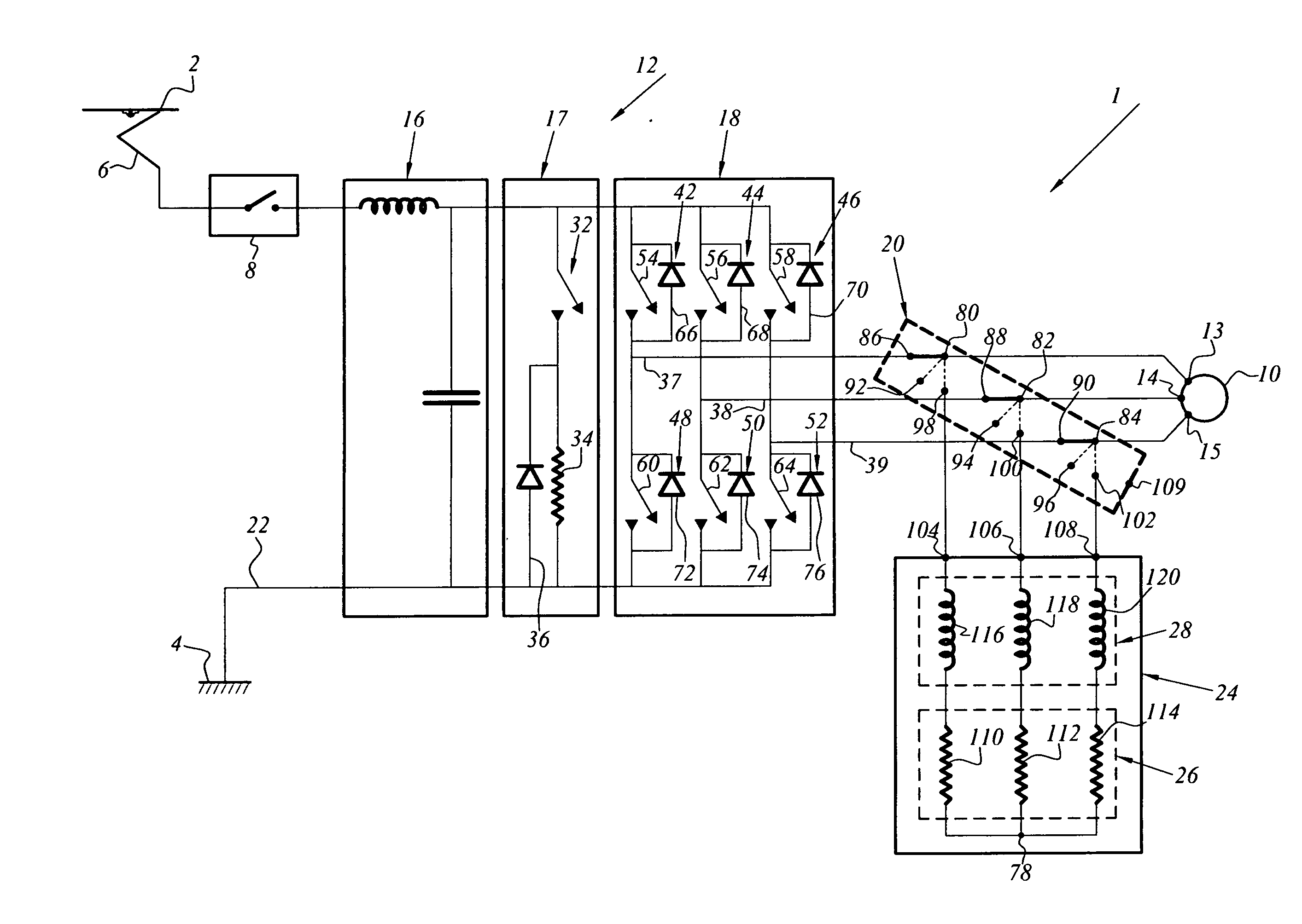
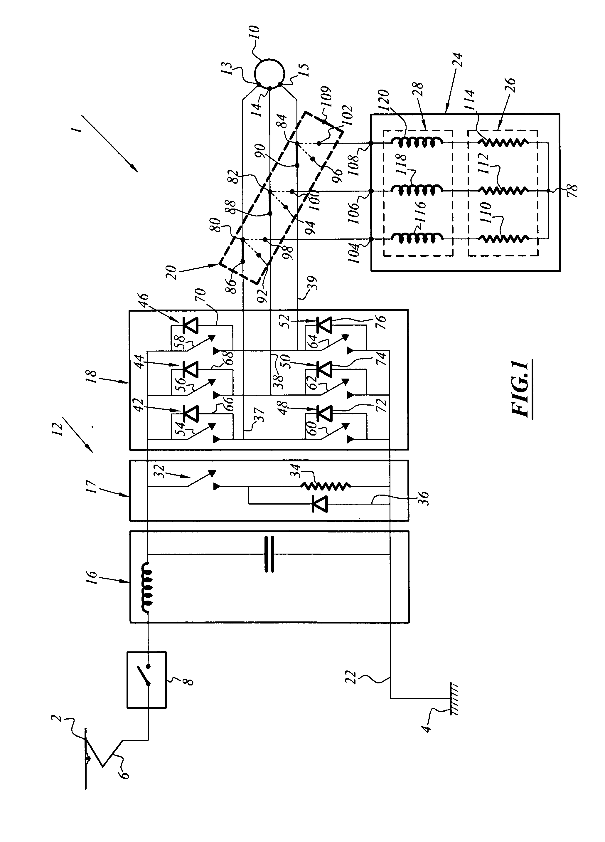
[0028]FIG. 1 illustrates an electric safety motor brake integrated in an electric traction chain 1 of a rail vehicle.

[0029]The electric traction chain 1 is supplied with electrical power by means of a catenary line (or a third rail) 2 which is under high voltage and which is referenced by a ground 4 which is connected to the earth.

[0030]The electric traction chain 1 comprises, in sequence, a pantograph (or skate) 6 for capturing electrical energy from the catenary line 2 followed by a line circuit-breaker 8 which acts as a main switch / contactor between the traction chain 1 and the catenary line 2.

[0031]The traction chain 1 also comprises a rotating electromechanical machine 10 which is in a state of permanent excitement and which is capable of being supplied with electrical power via an electronic power converter 12.

[0032]The rotating electromechanical machine 10 in this instance comprises a stator which has coils having a three-phase power supply and which is provided with electric...


PUM


Abstract

This electric safety braking device for an electric traction vehicle may allow the force/speed characteristic of the vehicle to be improved and includes a rotating electromechanical machine with permanent magnets which has at least one coil with electric terminals, a rheostatic electric braking torque production device, and a commutation device which are capable of connecting the electric terminals of the electromechanical machine to the braking torque production device. The electric safety braking device includes at least one inductor is connected in series between the braking torque production device and the electromechanical machine.

Description

[0001]This claims the benefit of FR 07 57339 filed on Sep. 4, 2007 and hereby incorporated by reference herein.[0002]The invention relates to an electric safety braking device which has braking torque control and which is intended for a vehicle which is electrically driven, for example, a rail vehicle.BACKGROUND OF THE INVENTION[0003]A safety braking system ensures the desired braking force is produced in an extremely reliable manner.[0004]In the field of rail transport, there are principally two types of braking operation: service braking and emergency braking.[0005]The service braking operation is the one which is most commonly used during operation. It can be adjusted between a minimum force value close to 0 and a maximum force value. It can be broken down itself into a plurality of modes, depending on the trains: purely electric brake, purely mechanical brake or combined electric and mechanical brake. It carries out all the “normal” stopping and deceleration operations of the tr...

Claims


Application Information

Patent Timeline
IPC IPC(8): H02P3/22
CPCB60L7/003H02P3/22B60L2200/26Y02T10/642H02P6/24Y02T10/64B61H1/00
Inventor JOBARD, THIERRYBONIN, ERIC
Owner ALSTOM TRANSPORT TECH SAS
Why Eureka
Try Eureka