Transformer Meter and System for Using Same

a transformer meter and transformer technology, applied in the field of transformer meter, can solve the problems of inability to monitor the current of the distribution transformer, the meter used to monitor the distribution transformer is bulky, and the current monitoring of the distribution transformer is not always possible, so as to achieve easy installation and high accuracy.

Inactive Publication Date: 2009-03-12
GRID2020
View PDF11 Cites 39 Cited by
  • Summary
  • Abstract
  • Description
  • Claims
  • Application Information

AI Technical Summary

Benefits of technology

[0004]In accordance with one aspect of the present invention, there is provided an improved meter for precisely measuring voltage and current and other data on a distribution transformer, the meter being both easy to install and highly accurate. The meter includes a housing having a body portion and a lever portion, the lever portion being movably connected to the body portion and movable between a closed position wherein the lever portion abuts the body portion and an open position wherein the lever portion is positioned away from the body portion. The meter includes first and second current sensors each divided into two corresponding sensor fractions with one fraction of each sensor formed on the body portion of the housing and the other corresponding fraction of each sensor formed on the lever portion of the housing. The fractions of the first and second current sensors are configured such that each of the first and second curren

Problems solved by technology

Traditionally, the meters used to monitor distribution transformers have been bulky devices incorporating either solid core or split core current sensors coupled to an instrumentation module.
While solid core and split core current sensors have been used to reliably measure current, they are prone to errors resulting from the non-linear characteristics of ferromagnet

Method used


Image

  • Transformer Meter and System for Using Same
  • Transformer Meter and System for Using Same
  • Transformer Meter and System for Using Same

Examples


Embodiment Construction

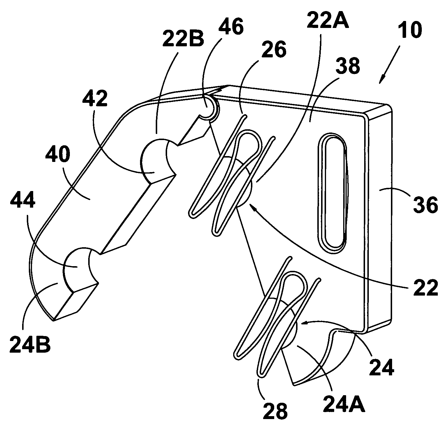
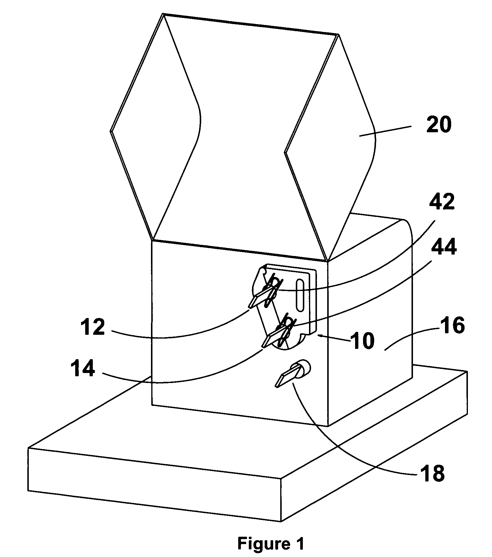
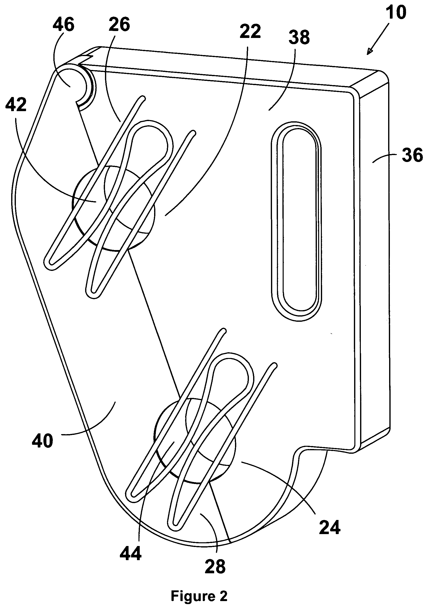
[0039]Referring firstly to FIG. 1, the present invention comprises, in part, an improved distribution transformer meter, shown generally as item 10, which is configured to be mounted to terminals 12 and 14 of distribution transformer 16 and which is further configured to record voltage, current, temperature, energy and AIPC measurements from the transformer and to communicate those measurements to a remote user, not shown. Transformer 16 is a distribution transformer, which may be either a pad mounted transformer, as illustrated in FIG. 1, or a pole mounted distribution transformer as illustrated in FIG. 29. The present invention is well suited for use with pad mounted distribution transformers but can be modified for use on pole mounted transformers as well. Pad mounted distribution transformer 16 will have terminals 12 and 14 representing the X1 and X3 terminals, and a neutral (X2) terminal 18. Cover 20 is provided on transformer 16 to protect the terminals against the elements.

[0...


PUM


Abstract

The present invention is a meter for recording voltage and current on a transformer. The device has a housing with a body portion and a lever portion, the lever portion being movable between a closed position wherein the lever portion abuts the body portion and an open position wherein the lever portion is positioned away from the body portion. The device includes a pair of current sensors each current sensor being divided into two corresponding sensor fractions with one fraction of each sensor formed on the body portion of the housing and the other corresponding fraction formed on the lever portion of the housing. The fractions of each sensors are constructed such that each of the current sensors have a central opening dimensioned to receive one of the transformer terminals when the lever portion of the housing is in its first position. The current sensors are positioned on the housing such that the meter can be mounted to the terminals of the transformer. The device also includes two voltage leads which can be attached to the transformers terminals. An instrumentation module is contained in the housing and is coupled to the current sensors and the voltage leads, the instrumentation module being adapted and configured to record voltage and current measurements from the current sensors and voltage leads. The instrumentation module includes a signal processing module for processing the voltage and current signals to provide other information such as energy and accumulated in-phase current 90 data. Finally, the device includes a communications module coupled to the instrumentation module for communicating the voltage and current measurements and the derived data to a remote user.

Description

CROSS REFERENCE TO RELATED APPLICATION[0001]This application claims priority from U.S. provisional patent application Ser. No. 60 / 949,606 filed Jul. 13, 2007, the entirety of which is incorporated herein by reference.FIELD OF THE INVENTION[0002]The invention relates generally to transformer meters for recording voltage and current measurements and other data from the transformer and transmitting same to a remote user.BACKGROUND OF THE INVENTION[0003]Distribution transformer meters have been used to monitor the condition of distribution transformers and to measure the electrical energy being consumed by loads coupled to the distribution transformer. Traditionally, the meters used to monitor distribution transformers have been bulky devices incorporating either solid core or split core current sensors coupled to an instrumentation module. While solid core and split core current sensors have been used to reliably measure current, they are prone to errors resulting from the non-linear c...

Claims


Application Information

Patent Timeline
IPC IPC(8): G01R19/00G01R7/00G01R15/18
CPCG01R15/18G01R22/06H04B2203/5433H04B3/56H04B3/54G01R15/181
Inventor DE BUDA, ERIC
Owner GRID2020
Why Eureka
Try Eureka