Power Converter Employing a Micromagnetic Device

a micro-magnetic device and power converter technology, applied in the field of micro-magnetic devices, can solve the problems that the process is not suitable for manufacturing a substantial number of integrated micro-magnetic devices

Active Publication Date: 2009-03-12
INTEL CORP
View PDF99 Cites 40 Cited by
  • Summary
  • Abstract
  • Description
  • Claims
  • Application Information

AI Technical Summary

Benefits of technology

[0009]These and other problems are generally solved or circumvented, and technical advantages are generally achieved, by advantageous embodiments of a power converter including a power train, a controller and a driver. In one embodiment, the power train includes a switch configured to conduct for a duty cycle and provide a regulated output characteristic at an output of the power converter, and a micromagnetic device interposed between the switch and the output of the power converter. The micromagnetic device includes a substrate, and a magnetic core layer formed over the substrate from a magnetic alloy. The magnetic alloy includes iron, cobalt and phosphorous. A content of the cobalt is in a range of 1.8 to 4.5 atomic percent. A content of the phosphorus is in a range of 20.1 to 30 atomic percent. A content of the iron is substantially a remaining proportion of the magnetic alloy. The controller of the power converter is configured to provide a signal to control the duty cycle of the switch. The driver of the power converter is configured to provide a drive signal to the switch as a function of the signal from the controller.

Problems solved by technology

Thus, although substantial progress has been made in development of techniques for production of a highly integrated power converter that is formed on a single chip, these processes are not suitable for manufacturing an integrated micromagnetic device in substantial numbers and with the process yields and repeatability necessary to produce the reliability and cost for an end product.

Method used


Image

  • Power Converter Employing a Micromagnetic Device
  • Power Converter Employing a Micromagnetic Device
  • Power Converter Employing a Micromagnetic Device

Examples


Embodiment Construction

[0023]The making and using of embodiments are discussed in detail below. It should be appreciated, however, that the invention provides many applicable inventive concepts that can be embodied in a wide variety of specific contexts. The specific embodiments discussed are merely illustrative of specific ways to make and use the invention, and do not limit the scope of the invention.

[0024]The invention will be described with respect to exemplary embodiments in a specific context, namely, a micromagnetic device, method of forming the same and a power converter employing the same. Additionally, an electroplating tool and electrolyte employable for constructing a magnetic core layer of the micromagnetic device will also be described herein. Also, a method of processing a substrate and micromagnetic device to relieve stress induced by a conductive film will be described herein.

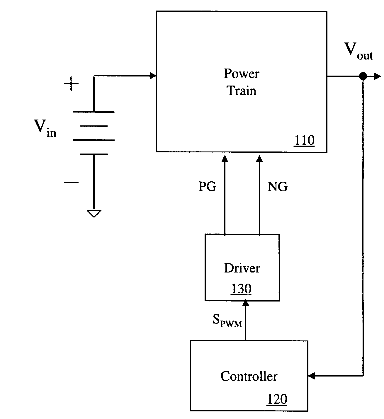
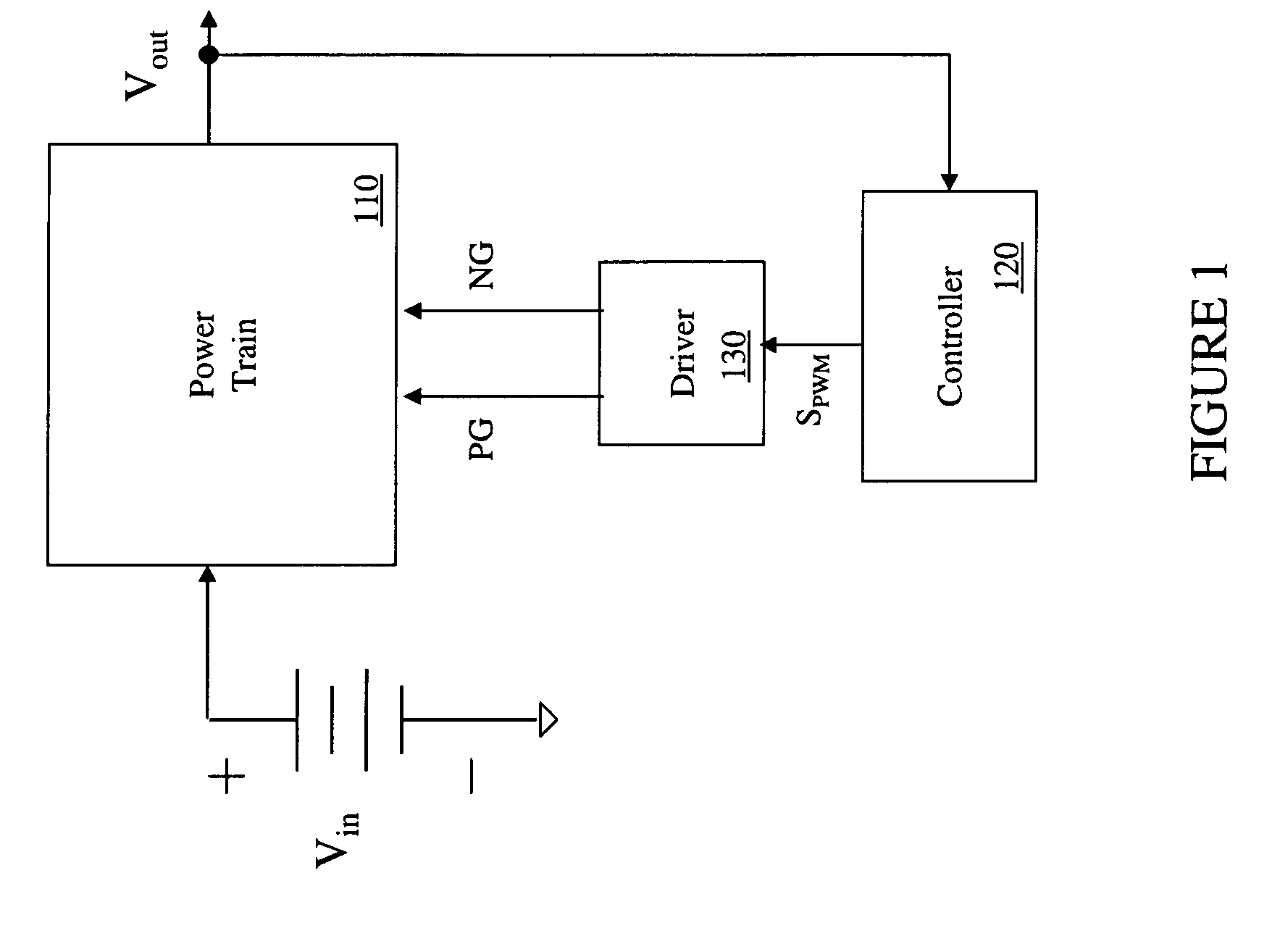
[0025]Referring initially to FIG. 1, illustrated is a block diagram of an embodiment of a power converter includin...


PUM

PropertyMeasurementUnit
bias voltageaaaaaaaaaa
switching frequencyaaaaaaaaaa
currentaaaaaaaaaa

Abstract

A power converter including a power train, a controller and a driver. The power train includes a switch that conducts for a duty cycle and provides a regulated output characteristic for the power converter, and a micromagnetic device interposed between the switch and the output of the power converter. The micromagnetic device includes a substrate, and a magnetic core layer formed over the substrate from a magnetic alloy including iron, cobalt and phosphorous. A content of the cobalt is in a range of 1.8 to 4.5 atomic percent. A content of the phosphorus is in a range of 20.1 to 30 atomic percent. A content of the iron is substantially a remaining proportion of the magnetic alloy. The controller provides a signal to control the duty cycle of the switch. The driver provides a drive signal to the switch as a function of the signal from the controller.

Description

TECHNICAL FIELD[0001]The invention is directed, in general, to magnetic devices and, more specifically, to a micromagnetic device, method of forming and power converter employing the same, and an electroplating tool and electrolyte employable for constructing a magnetic core layer of the micromagnetic device, and a method of processing a substrate and micromagnetic device.BACKGROUND[0002]A switch mode power converter (also referred to as a “power converter”) is a power supply or power processing circuit that converts an input voltage waveform into a specified output voltage waveform, which is typically a well-regulated voltage in electronic device applications. Power converters are frequently employed to power loads having tight voltage regulation characteristics such as a microprocessor with, for instance, a bias voltage of one volt or less provided by the power converter. To provide the voltage conversion and regulation functions, power converters include a reactive circuit elemen...

Claims


Application Information

Patent Timeline
Patent Type & Authority Applications(United States)
IPC IPC(8): H01F27/24G05F1/00
CPCH01F10/132H01F10/138H01F10/265H01F41/046H01L2224/11
Inventor LOTFI, ASHRAF W.LIAKOPOULOS, TRIFON M.FILAS, ROBERT W.
Owner INTEL CORP
Why Eureka
Try Eureka