

Display and method of manufacturing the same
a technology of display and manufacturing method, which is applied in the manufacture of electrode systems, electric discharge tubes/lamps, instruments, etc., can solve the problems of degradation in display quality, inability to obtain reliable sealing between a pair of substrates, and difficulty in accurately supplying the seal member to a predetermined seal region. achieve the effect of easy and accurate formation
- Summary
- Abstract
- Description
- Claims
- Application Information
AI Technical Summary
Benefits of technology
Problems solved by technology
Method used
Image


Examples
first preferred embodiment
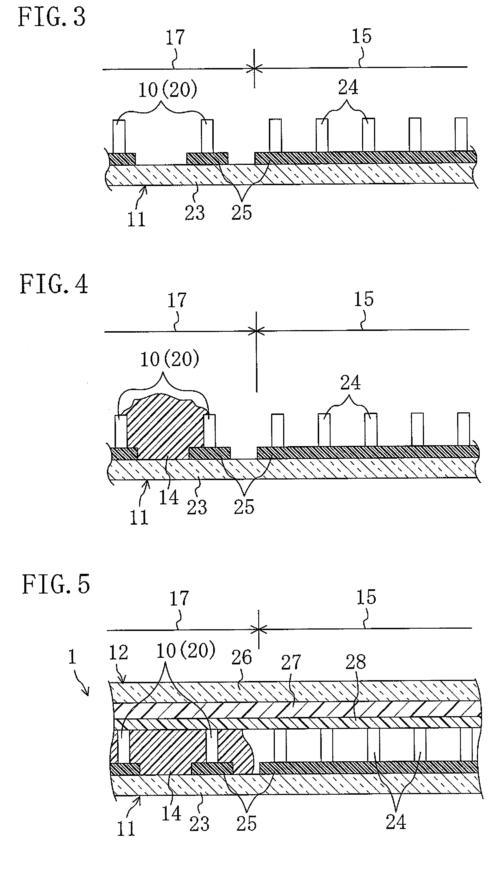
[0044]FIGS. 1 through 5 show a first preferred embodiment of the present invention. In this preferred embodiment, a liquid crystal display device will be described as an example of a display device.
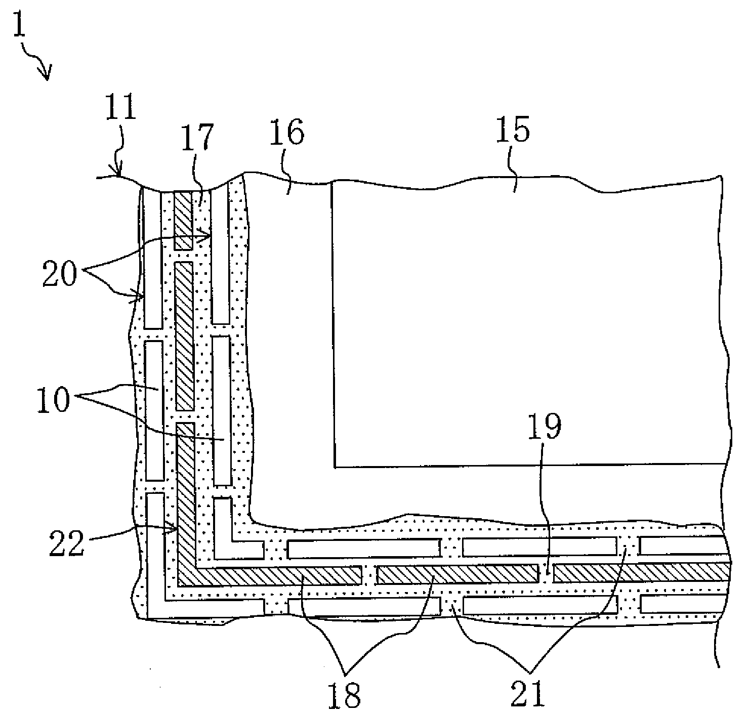
[0045]FIG. 1 is a partial enlarged plan view of a liquid crystal display device 1. FIG. 2 is a cutaway section showing a part of the liquid crystal display device 1. FIGS. 3 through 5 are cross-sectional views illustrating a manufacturing process of the liquid crystal display device 1.
[0046]The liquid crystal display device 1 includes a first substrate 11 and a second substrate 12 which are bonded to each other with spacers 10 interposed therebetween, and a liquid crystal layer 13 (shown in FIG. 9) which is a display medium layer provided between the first substrate 11 and the second substrate 12. The liquid crystal layer 13 is surrounded and sealed by an approximately frame-shaped seal member 14 between the first substrate 11 and the second substrate. The liquid crystal display device 1 ...
second preferred embodiment
[0077]FIGS. 10 and 11 show a second preferred embodiment of the invention. Note that in each preferred embodiment described below, the same portions as those of FIGS. 1 through 9 are denoted by the same reference numerals and detailed description thereof will be omitted.
[0078]The second preferred embodiment is different from the first preferred embodiment in that the shape of the spacer rows 20 is different. More specifically, in the first preferred embodiment, the spacers 10 of the spacer rows 20 preferably have an elongated shape so as to extend approximately in parallel with the four sides of a rectangle along the outer edge of the display region 15 (as shown in FIG. 1). Spacers 10 of this preferred embodiment, on the other hand, are slightly tilted with respect to the four sides along the outer edge of the display region 15. As shown in a plan view of FIG. 10, each spacer 10 has a wide open approximately V-shaped form. At the corners of the spacer rows 20, the spacer 10 may eith...
third preferred embodiment
[0081]FIGS. 12 and 13 show a third preferred embodiment of the present invention.
[0082]Spacers 10 of the third preferred embodiment are patterned to have a hook shape extending along the outer edge of the display region 15. More specifically, as shown in a plan view of FIG. 12, a protruding portion 10a protruding toward the display region 15 side or toward the opposite side to the display region 15 is provided at both ends of each spacer 10. For example, in one of the two spacer rows 20 that are located on the display region 15 side, a protruding portion 10a protruding toward the opposite side to the display region 15 is provided at both ends of the spacer 10 having an elongated shape. In the other spacer row 20 located on the opposite side to the display region 15, on the other hand, a protruding portion 10a protruding toward the display region 15 is provided at both ends of the spacer 10.
[0083]The same effects as those of the first preferred embodiment can be obtained even when th...
PUM
 Abstract
Description
Claims
Application Information