
Tint block image generation program and tint block image generation device

a technology of image generation and tint block, which is applied in the field of tint block image generation program and tint block image generation device, can solve the problems of inability to reproduce perfectly in a copy, the inability of the copying machine to reproduce perfectly, and the disappearance of isolated micro dots, so as to achieve the effect of reducing the concealment capability of the original image and high accuracy

Active Publication Date: 2009-03-12
SEIKO EPSON CORP
View PDF4 Cites 17 Cited by
  • Summary
  • Abstract
  • Description
  • Claims
  • Application Information

AI Technical Summary

Benefits of technology

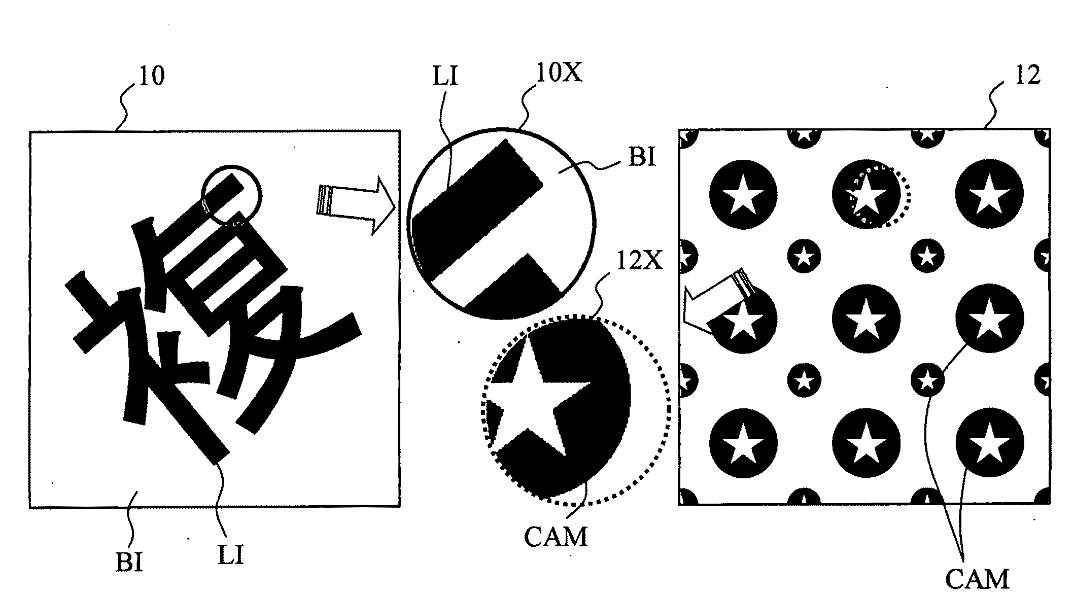
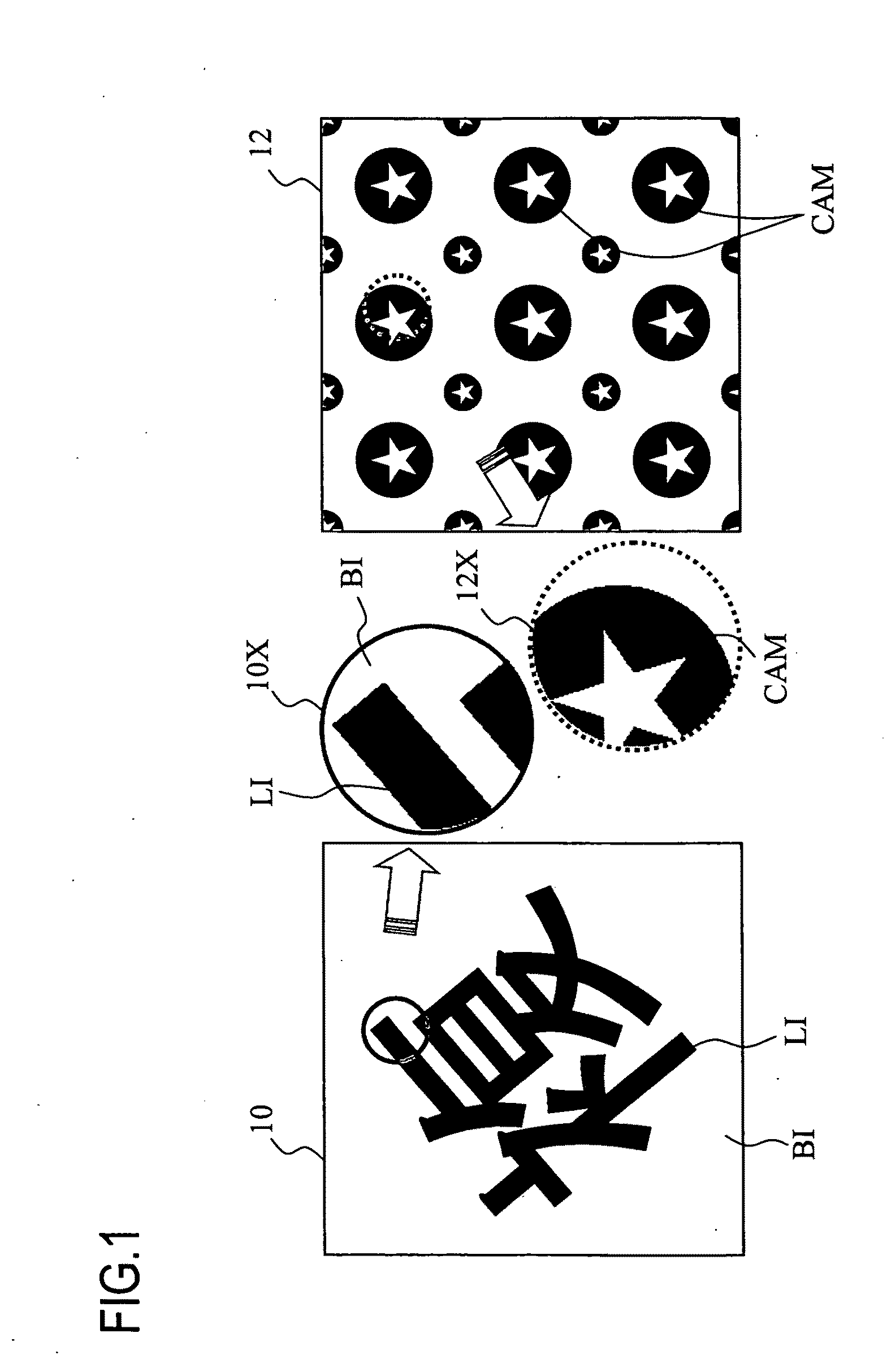
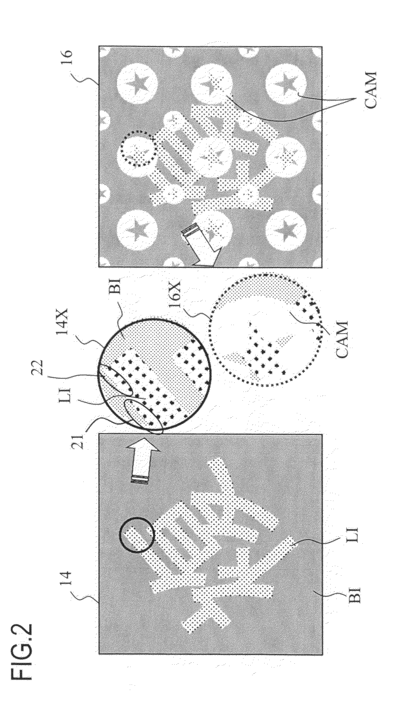
[0025]However, in the case of this second problem, dots are formed at high screen ruling in the background portion BI, so the dots OFF area is generated corresponding to the camouflage pattern with high resolution, and the pattern is reproduced at relatively high accuracy in the background portion BI, whereas in the latent image portion LI, dots are formed at low screen ruling, so the dots OFF area generated corresponding to the camouflage pattern becomes rough, and appearance of the pattern becomes different from the background portion. For example, the dots OFF area is generated relatively large in area 27 in FIG. 7. If the appearance of the camouflage pattern is different between the background portion and the latent image portion, the latent image stands out, and concealment capability for the latent image of the original is diminished.

Problems solved by technology

Generally a copier has a limitation in image reproducing capability, which depends on the input resolution in a step of reading the micro dots of a copy target original by a scanner, and the output resolution in a step of reproducing micro dots, read by the scanner, using a print engine.
Therefore if isolated micro dots exist in the original, exceeding the limitation of the image reproducing capability of the copier, the micro dots cannot be perfectly reproduced in a copy, and the portions of the isolated micro dots disappear.

Method used


Image

  • Tint block image generation program and tint block image generation device
  • Tint block image generation program and tint block image generation device
  • Tint block image generation program and tint block image generation device

Examples


second embodiment

[0228]Now a second embodiment, applying the present invention to an image other than the tint block image, will be described. In the above embodiment, the tint block having the latent image portion and the background portion was described. The present invention, however, can also be applied to a general image where 2 areas, in which a screen processing using an AM screen with low screen ruling and a screen processing using an AM screen or an FM screen based on an error diffusion method or dispersed dither matrix, with a screen ruling are performed respectively.

[0229]FIG. 41 is a flow chart depicting an image data generation procedure according to the second embodiment. FIG. 42 shows an image example according to the second embodiment. The image data generation procedure in FIG. 41 will be described with reference to FIG. 42.

[0230]First the image data generation program is executed on the host computer to generate image data (S61). As FIG. 42 shows, this image is comprised of a circu...


PUM


Abstract

A image generation device generates, on a print medium, an image including a first image portion and a second image portion. The device has a first screen processing unit which generates image data by an area modulation screen having a first screen ruling, for pixels of the first image portion; and a second screen processing unit which generates image data by an area modulation screen or a density modulation screen having a second screen ruling which is higher than the first screen ruling for pixels of the second image portion. And the first screen processing unit generates a halftone dot at a center of gravity position of an image of the first image portion in a cell corresponding to a halftone dot formation area in the area modulation screen processing.

Description

CROSS-REFERENCE TO RELATED APPLICATIONS[0001]This application is based upon and claims the benefit of priority from the prior Japanese Patent Applications No. 2007-231403, filed on Sep. 6, 2007, and No. 2008-181688, filed on Jul. 11, 2008, the entire contents of which are incorporated herein by reference.BACKGROUND OF THE INVENTION[0002]1. Field of the Invention[0003]The present invention relates to a tint block image generation program and a tint block image generation device, and more particularly to a program and device for generating tint block image data to be printed on a print medium. The present invention also relates to a tint block image generation program and generation device which has an effect to inhibit forgery by copying a print medium (original) on which a tint block image is printed based on the tint block data or an effect to distinguish between the original and the copy.[0004]2. Description of the Related Art[0005]The tint block is combined with the original imag...

Claims


Application Information

Patent Timeline
Patent Type & Authority Applications(United States)
IPC IPC(8): H04N1/405H04N1/40
CPCH04N1/00864H04N1/4055H04N1/00883
Inventor KOBAYASHIKARITO, NOBUHIRO
Owner SEIKO EPSON CORP
Learn More