
Rasp hand tool and method for using same to form and shape exterior insulation and finish system surfaces

Inactive Publication Date: 2009-03-12
ANGELISANTI JONATHAN
View PDF50 Cites 1 Cited by
  • Summary
  • Abstract
  • Description
  • Claims
  • Application Information

AI Technical Summary

Benefits of technology

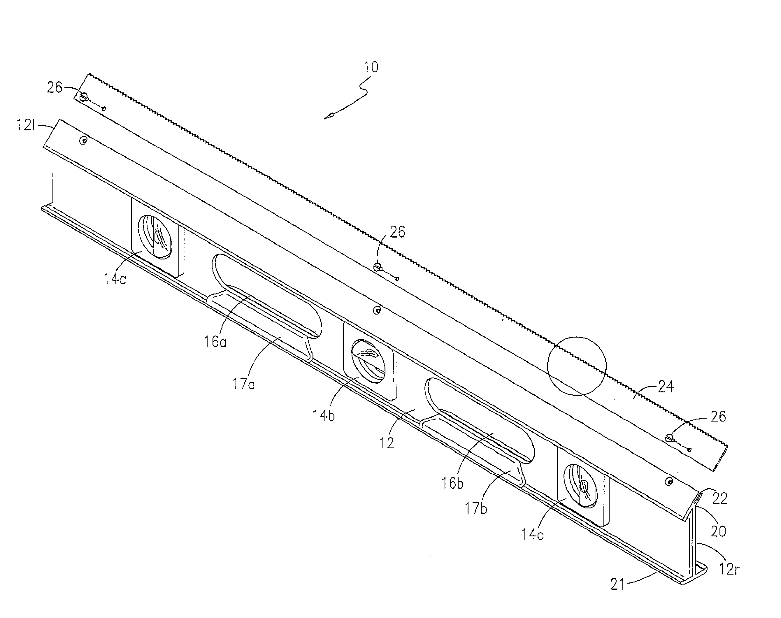
[0012]The present invention overcomes the limitations and disadvantages present in the art by providing an improved combination level and rasp tool particularly adapted for use in forming, shaping, and smoothing, EIFS surfaces. A combination level and rasp tool in accordance with the present invention includes an elongate frame having at least one level mounted thereto, a pair of spaced elongate hand hold apertures formed therein, and an elongate saw tooth rasp blade removably mounted to the frame and angularly disposed relation therewith. The upper portion of the frame preferably defines an angularly disposed elongate slot for receiving the rasp blade and suitable fasteners are provided for securely affixing the rasp blade. The rasp blade is configured to project angularly upward for ease of use.
[0013]Accordingly, it is an object of the present invention to provide an improved tool for forming, shaping, and smoothing EIFS surfaces.
[0015]Still another object of the present invention to provide such a tool wherein the rasp blade is angularly mounted to the frame for ease of use.

Problems solved by technology

With EIFS, skilled applicators can create all sorts of exterior architectural detailing that would often be cost-prohibitive using conventional construction.
These manual operations are tedious and time-consuming.
While the rasping tool disclosed by Cruz is somewhat effective in removing minor irregularities, the use of sand paper limits the effectiveness of the tool.
In addition, the rasping level disclosed by Cruz includes grippers that are relatively small, difficult to grasp, and place excessive strain on the users hands.

Method used


Image

  • Rasp hand tool and method for using same to form and shape exterior insulation and finish system surfaces
  • Rasp hand tool and method for using same to form and shape exterior insulation and finish system surfaces
  • Rasp hand tool and method for using same to form and shape exterior insulation and finish system surfaces

Examples


Embodiment Construction

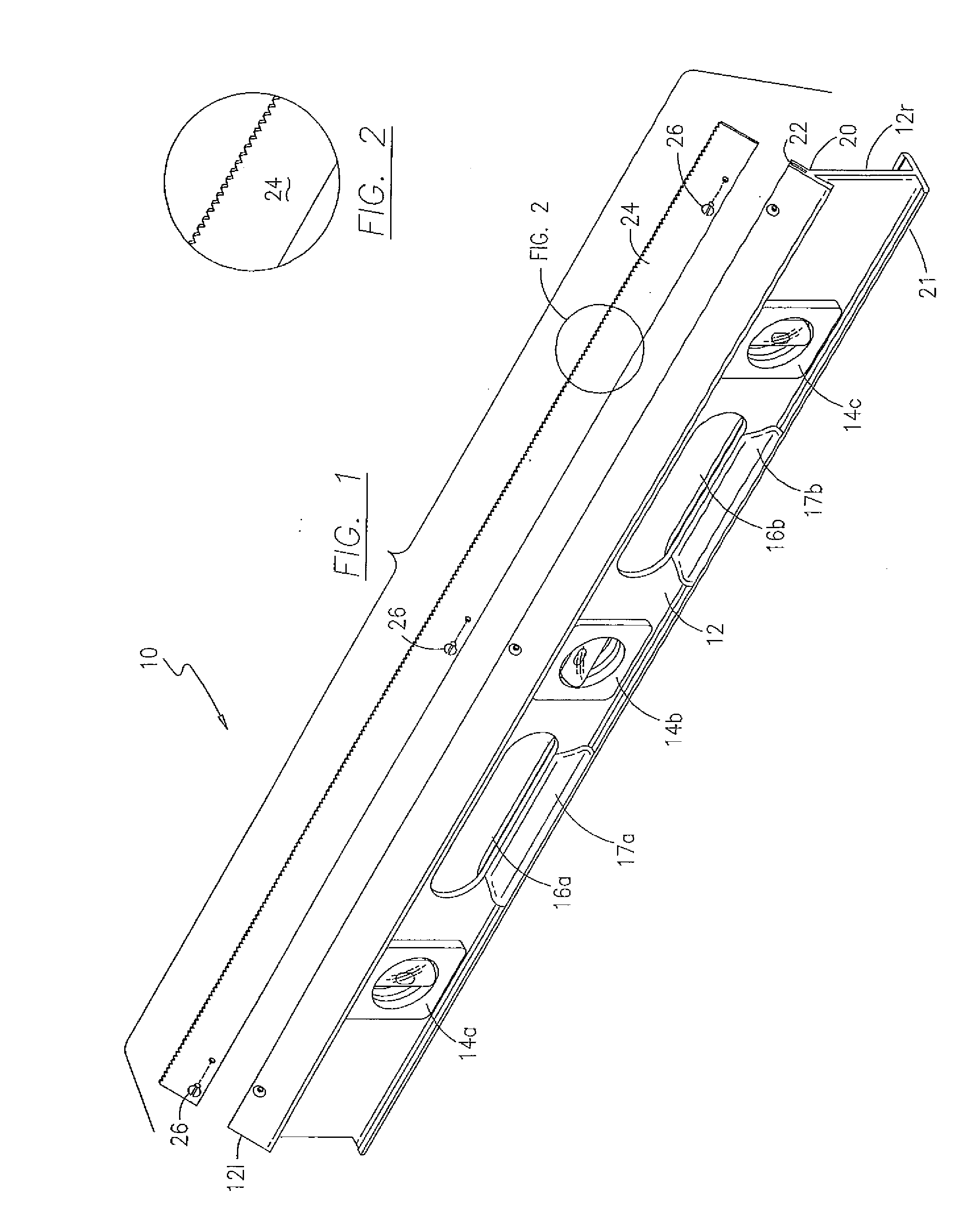
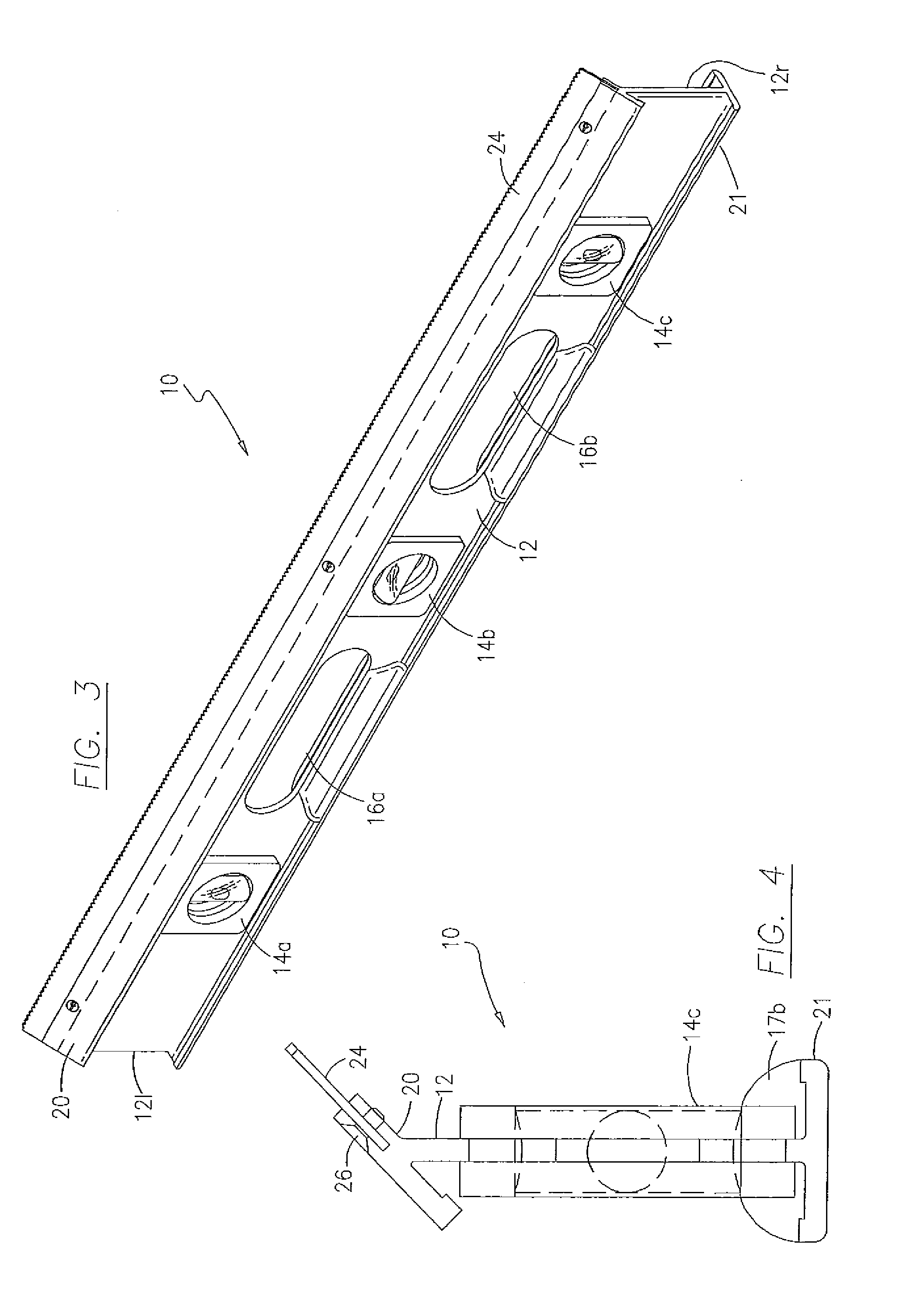
[0024]With reference to the drawings, FIGS. 1-4 depict an improved combination level and rasp tool, generally referenced as 10, in accordance with the present invention for use in forming, shaping, and smoothing, EIFS surfaces. Rasp tool 10 includes an elongate rigid frame member 12 having a left end 12l and a right end 12r. Frame member 12 is preferably fabricated from lightweight aluminum or composite material, however any suitable material is considered within the scope of the present invention. Frame member 12 includes a plurality of level members, referenced as 14a, 14b, and 14c, securely affixed thereto to allow the user to quickly determine horizontal and vertical orientations. As should be apparent, level members 14 may be oriented generally vertically, horizontally, and / or at a suitable angle. Frame member 12 further defines a pair of elongate slotted apertures, referenced as 16a and 16b that function to allow the user's hands to securely hold rasp tool 10 when in use. Fram...


PUM


Abstract

An improved combination level and rasp tool particularly adapted for use in forming, shaping, and smoothing, EIFS surfaces is disclosed. A combination level and rasp tool includes an elongate frame having at least one level mounted thereto, a pair of spaced elongate hand hold apertures formed therein, and an elongate saw tooth rasp blade removably mounted to the frame and angularly disposed relation therewith. The upper portion of the frame preferably defines an angularly disposed elongate slot for receiving the rasp blade and suitable fasteners are provided for securely affixing the rasp blade. The rasp blade is configured to project angularly upward for ease of use.

Description

CROSS REFERENCE TO RELATED APPLICATIONS[0001]This application claims the benefit of provisional U.S. Patent Application No. 60 / 993,594, filed Sep. 12, 2007.STATEMENT REGARDING FEDERALLY SPONSORED RESEARCH OR DEVELOPMENT[0002]N / ACOPYRIGHT NOTICE[0003]A portion of the disclosure of this patent document contains material that is subject to copyright protection. The copyright owner has no objection to the facsimile reproduction by anyone of the patent document or patent disclosure as it appears in the Patent and Trademark Office patent file or records, but otherwise reserves all copyrights rights whatsoever.BACKGROUND OF THE INVENTION[0004]1. Field of the Invention[0005]The present invention relates generally to hand tools, and more particularly to a rasp hand tool particularly suited for use in forming and sculpting exterior insulation and finish systems.[0006]2. Description of Related Art[0007]Exterior Insulation and Finish Systems (EIFS) are multi-layered exterior wall systems that a...

Claims


Application Information

Patent Timeline
IPC IPC(8): B24D15/00G01C9/00
CPCB24D15/02Y10T407/1825G01C9/28
Inventor ANGELISANTI, JONATHAN
Owner ANGELISANTI JONATHAN
Learn More