Electrically measuring expansions on cylindrical bodies

a cylindrical body and expansion technology, applied in the direction of mechanical solid deformation measurement, measurement devices, instruments, etc., can solve the problem of requiring relative complicated manipulation

Inactive Publication Date: 2009-03-19
BAUMER HLDG
View PDF4 Cites 3 Cited by
  • Summary
  • Abstract
  • Description
  • Claims
  • Application Information

AI Technical Summary

Benefits of technology

[0007]The invention is based on the object of providing a method and an apparatus of the type mentioned initially, which simplify the electrical measurement of positive and negative strains on the outer surface of essentially cylindrical bodies by means of a mobile clip-on instrument, and automate this process for the optimum position.
[0017]In all the embodiments, the clip-on instrument according to the invention has the advantage over a measurement ring that it is not associated with a single essentially cylindrical body, but can be replaced with a few actions, without releasing screws or the like, from a body in order to change this. In contrast to known clip-on instruments, the centering is carried out automatically and necessarily at the correct location.

Problems solved by technology

Furthermore, the measurement object must have an exactly circular section at the measurement point, and these sensors are not intended for oval profiles or those with corners.
However, relatively complicated manipulations are required for this purpose, and the optimum position must be searched for and set for each measurement.

Method used


Image

  • Electrically measuring expansions on cylindrical bodies
  • Electrically measuring expansions on cylindrical bodies
  • Electrically measuring expansions on cylindrical bodies

Examples


Embodiment Construction

)

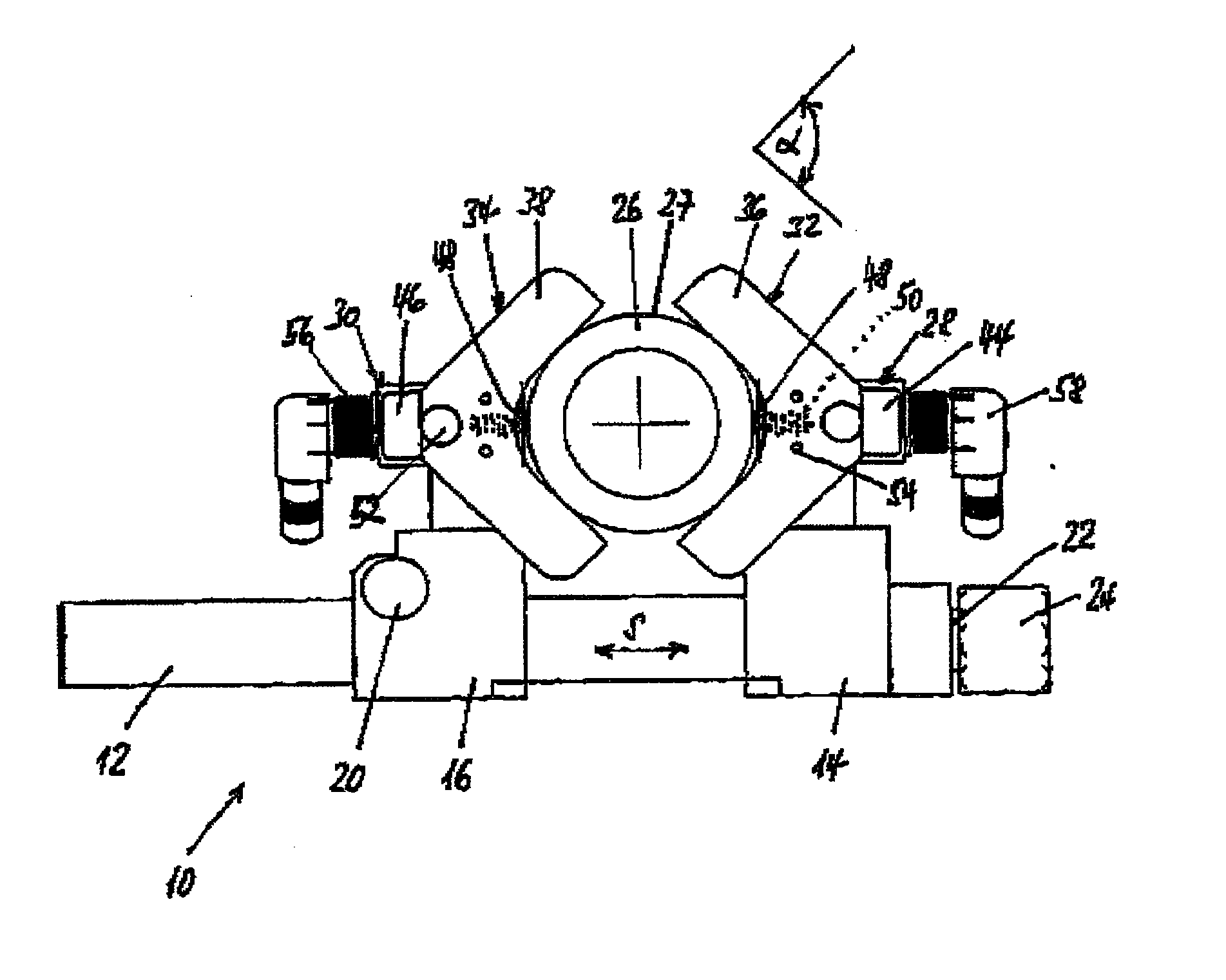
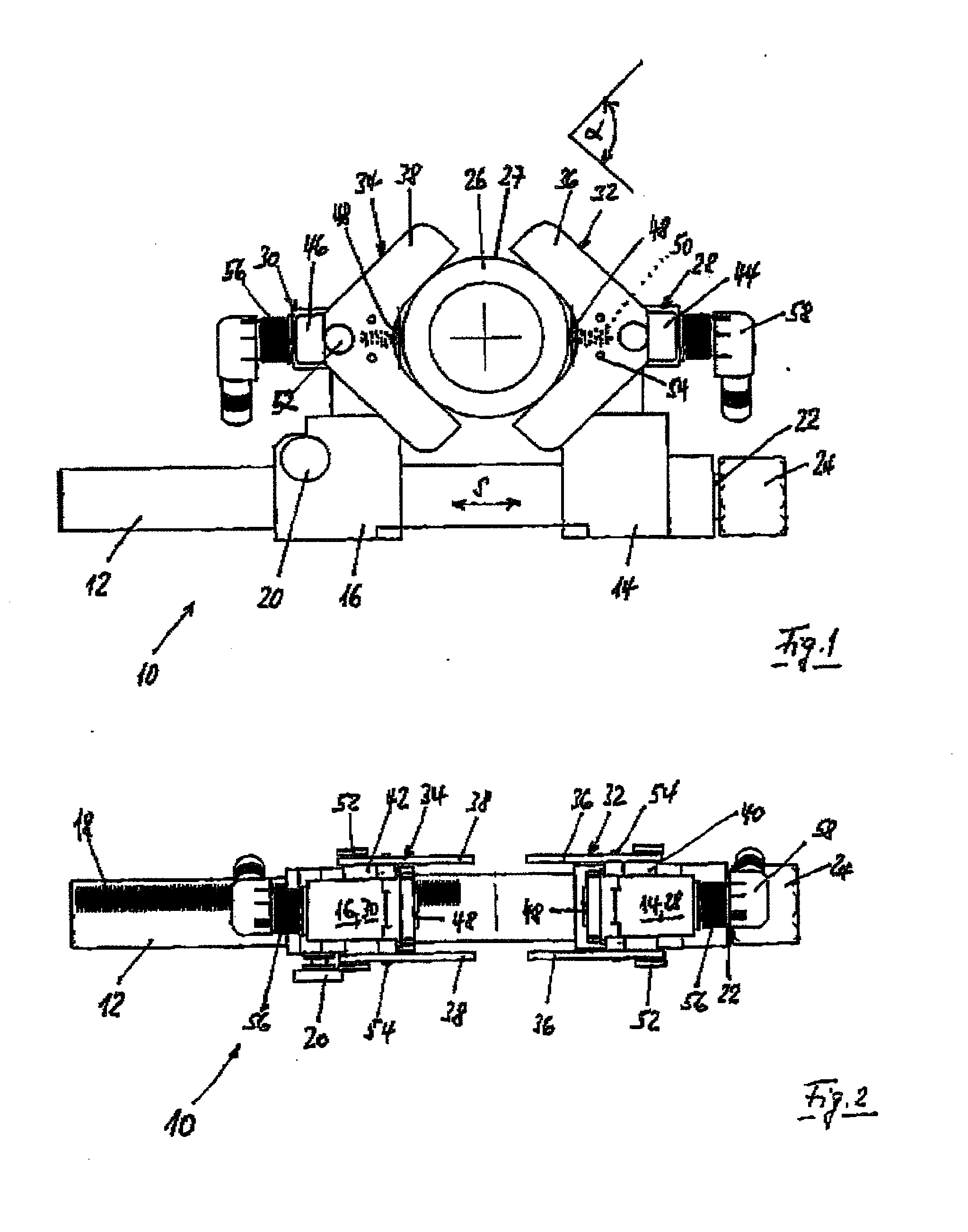
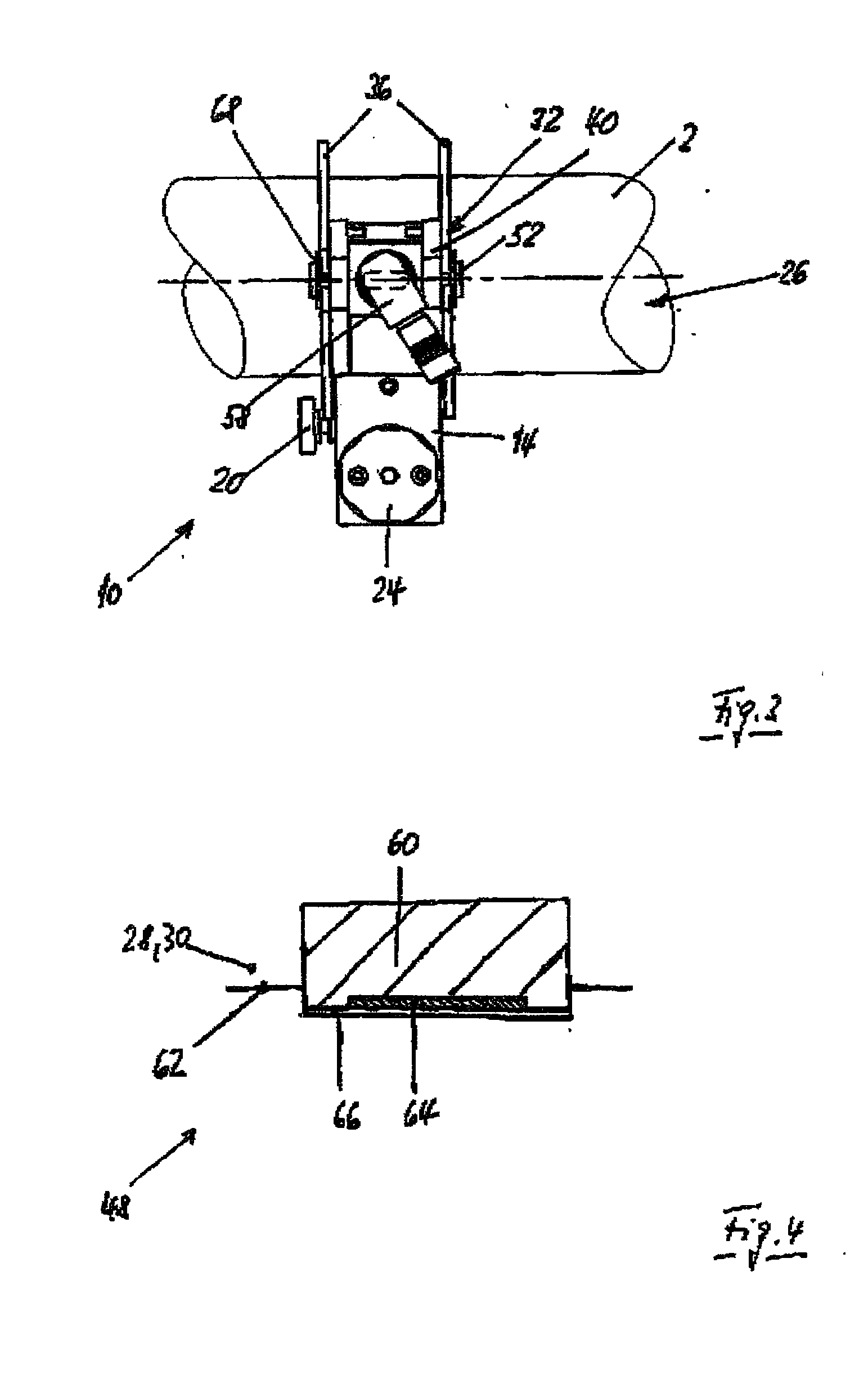
[0023]A mobile clip-on instrument 10 as shown in FIGS. 1 to 3 has a guide profile 12 with a cross section which in the present case is circular with a flat at the top. A first slide 14 and a second slide 16 are fitted to the guide profile 12, such that they cannot rotate. A toothed system 18 is formed in the area of the second slide 16, over a part of the circumference of the guide profile 12 (FIG. 2), with a comb interval of about 2 mm. The second slide 16 is unlatched from the toothed system 18 by an operating button 20, and can be moved freely along the guide profile 12. When the operating button 20 is released, a latching tab, which cannot be seen, on the second slide 16 latches in the toothed system 18, thus roughly positioning the second slide 16.

[0024]A spindle 22 which is fixed in the axial direction and has a short thread pitch passes through the first slide 14 in the tightening direction S, and engages in an internal thread. A torque setting 24 defines the maximum contact...


PUM

PropertyMeasurementUnit
angleaaaaaaaaaa
angleaaaaaaaaaa
sizeaaaaaaaaaa

Abstract

Positive and negative expansions on the covering surface of essentially cylindrical bodies are measured by mobile measuring pincers which comprise a guiding profile for two adjacently adjustable sliders which are used to clamp the body in a radial direction and to press at least one expansive measuring element on the covering surface by forming a frictional connection. Currently, a first slider, which can be displaced in the direction of clamping on the guide profile by a spindle, preferably comprising integrated torque adjustment, is offset with a centering element on the cylindrical head. Then, a second slider, which can be displaced on the guide profile is arranged with a centering element on the cylindrical body and engaged. The centering elements are clamped on the body between the sliders by pulling the spindle. The measuring element(s) are is / are pressed onto the covering surface of the body in order to form a positive connection. The sliders comprise a guide element for the centering elements of the cylindrical head in the head region thereof, which can be displaced counter to the resistance of at least one return spring in the direction of clamping (S). The centering elements have, preferably, essentially angular centre plates which can be exchanged.

Description

BACKGROUND OF THE INVENTION[0001](1) Field of the Invention[0002]The invention relates to a method and an apparatus for electrical measurement of positive and negative strains on the outer surface of essentially cylindrical bodies, using a mobile clip-on instrument which has a guide profile for two slides, which can be adjusted with respect to one another, for clamping a body in the radial direction and for pressing at least one strain-sensitive measurement element onto the outer surface, forming a force fit.[0003](2) Prior Art[0004]It is known for positive and negative strains on cylindrical bodies to be measured by exerting a high contact force on a measurement element. CH 887645 A5 describes a measured-value sensor in which an elastic element is pressed with the aid of two circular-ring halves onto the outer surface of the cylindrical body such that the strains which occur on its outer surface can be measured, by means of a force fit. Furthermore, the measurement object must have...

Claims


Application Information

Patent Timeline
Patent Type & Authority Applications(United States)
IPC IPC(8): G01N3/02
CPCG01B7/16G01B5/30
Inventor SCHMID, JEAN-JACQUES
Owner BAUMER HLDG
Why Eureka
Try Eureka