Method for shifting actuation of an automated group transmission

a technology of automatic group transmission and shifting actuation, which is applied in the direction of gearing control, gearing elements, gearing, etc., can solve the problems of delay in the reaching of the synchronous rotational speed of the prime mover to be expected prior to the activation of the target ratio stage of the range change group, and the limitation of the whole group transmission for future designs of such group transmissions. , to achieve the effect of quick opening and acceptable shifting comfor

Inactive Publication Date: 2009-03-19
ZF FRIEDRICHSHAFEN AG
View PDF8 Cites 21 Cited by
  • Summary
  • Abstract
  • Description
  • Claims
  • Application Information

AI Technical Summary

Benefits of technology

[0028]During the load reduction of the prime mover in the first method step SH1, the separating clutch K has advantageously been already partly disengaged to above the slip limit. Hereby the separating clutch K consecutively can be more quickly opened, since then no waiting time results for the prior filling of the clutch actuator with pressure medium and for the bypass of the idle stroke of the clutch actuator device.
[0029]During activation of the target ratio stages G1, G1′, S of the main transmission and / or of the range change group GP, that is, in method steps SH6a or SH6b, if the occurrence of a tooth-on-tooth position is found on the dog clutch concerned, then the shifting sequence is conveniently continued while maintaining the concerned engagement adjusting force, since the tooth-on-tooth position is removed by a consecutive necessarily occurring relative rotation of the transmission shafts involved (WVG1,WH;WVG,WH;WH,WGA) and the dog clutch can be engaged then without delaying the shifting sequence.
[0030]The inventive method essentially relates to the fact that the dog shifted transmission part of the group transmission, that is, the main transmission HG, HG′ and the range change group GP rear-mounted thereon, during a range change upshift is only roughly synchronized via the transmission brake Br and that the precise rotational speed adaptation of the transmission shafts WGE, WVG1, WVG2, WVG, WH, WGA thus occurs passively via the edge beveling of the dog clutches of the concerned shift sets S2, S2′, SP. Herefrom results in relation to the selected series of the method steps, a total shifting time as short as possible of the range change upshift with acceptable shifting comfort.

Problems solved by technology

But since many gear shifts in a group transmission require the change of ratio stages in several parts of the transmission and thus the sequence is relatively complicated, most known group transmissions are constructed such that they are either partly automated or fully automatedly shiftable.
But since the concerned synchronized shift clutches, due to a complicated construction, are relatively more expensive, need a relatively large amount of space and, as a result of wear, the duration of the whole group transmission is limited for future designs of such group transmissions.
It is, of course, disadvantageous in this known method that the existence of a front-mounted group or of a splitter group front-mounted on the main transmission is presupposed and that the shifting sequence can only be used in a range change upshift, similarly the reaching of the synchronous rotational speed by the prime mover to be expected prior to the activation of the target ratio stage of the range change group is delayed.

Method used


Image

  • Method for shifting actuation of an automated group transmission
  • Method for shifting actuation of an automated group transmission
  • Method for shifting actuation of an automated group transmission

Examples


Embodiment Construction

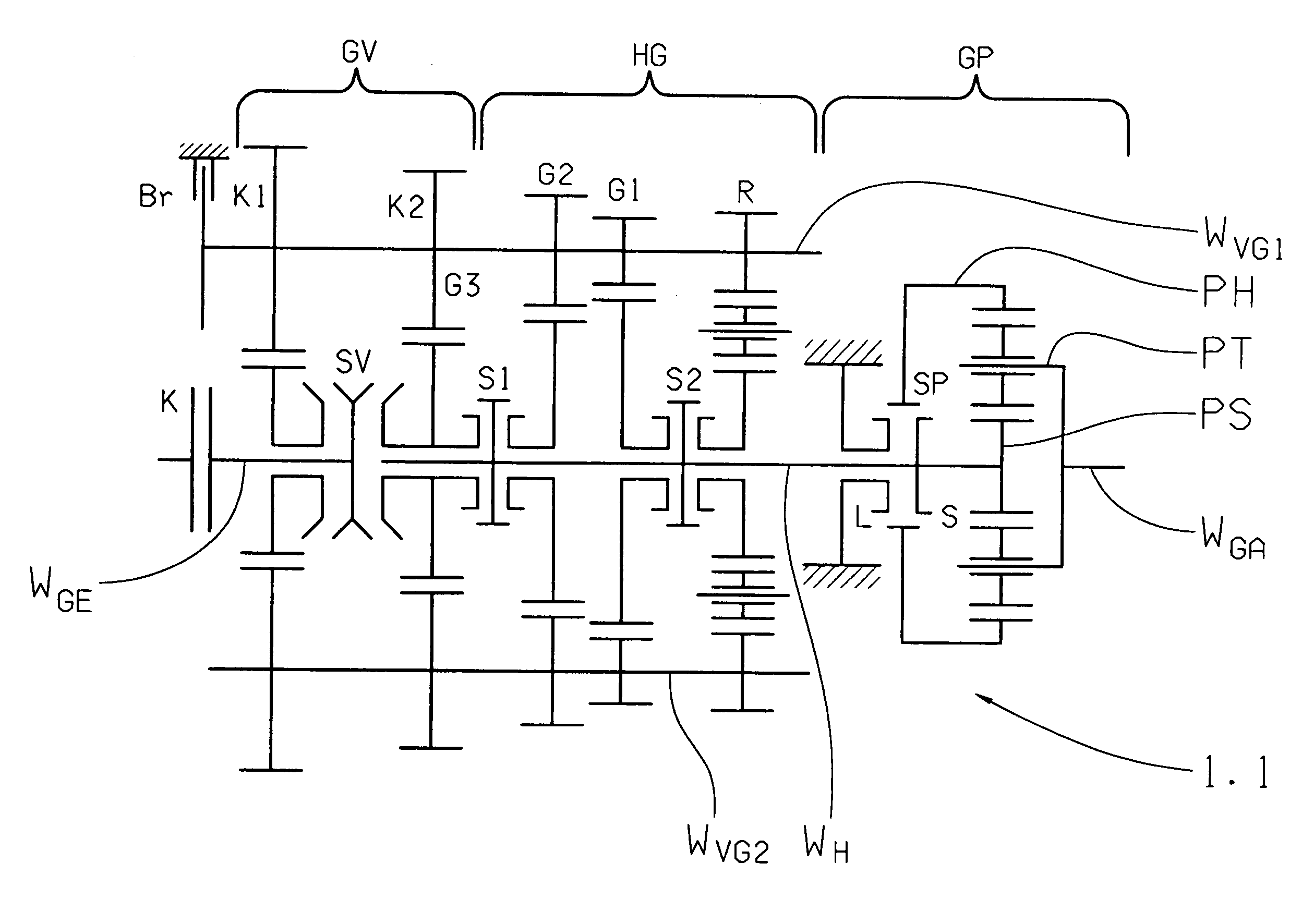
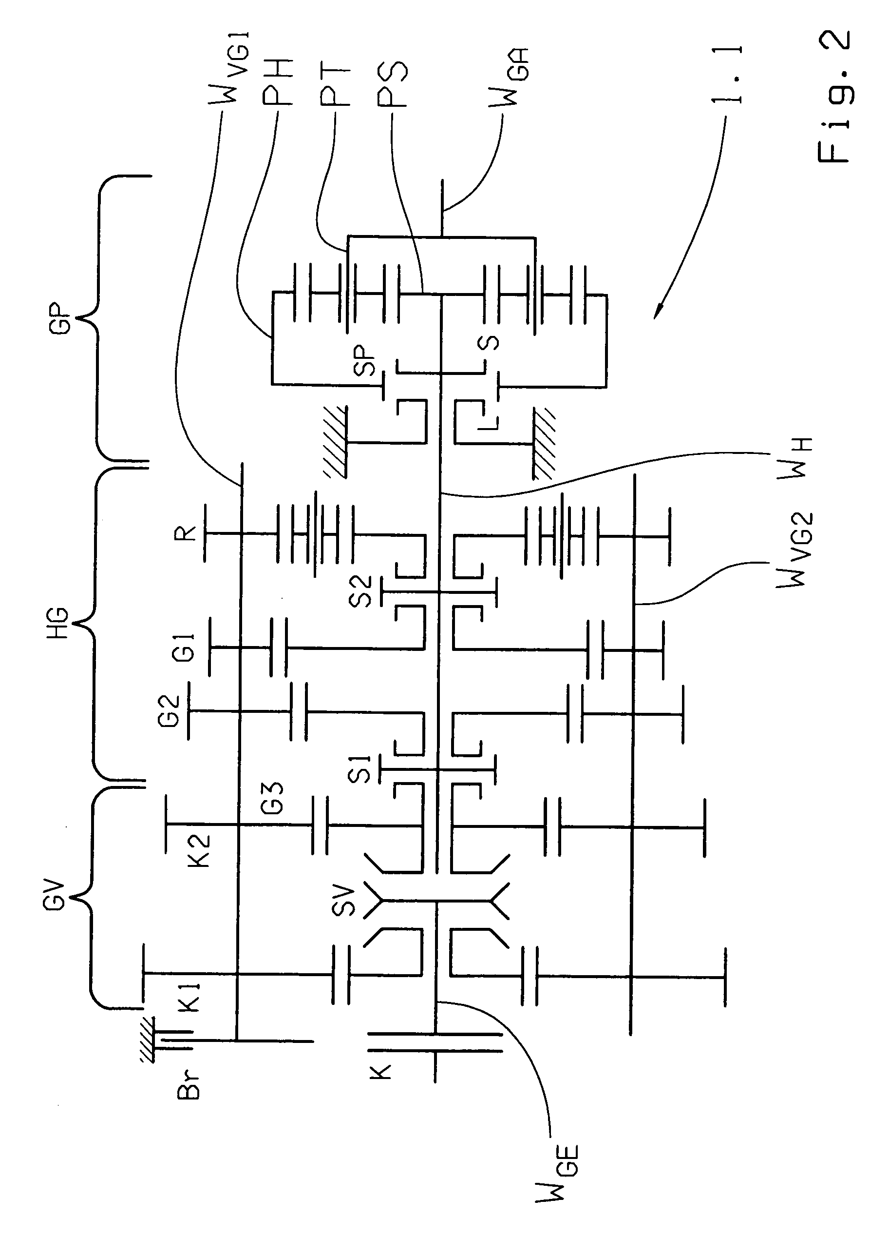
[0036]In FIG. 2 is shown a group transmission 1.1 where the inventive method can be used. The group transmission 1.1 comprises one main transmission HG, one group GV front-mounted thereon by drive technology and one range change group GP rear-mounted or rear placed thereon by drive technology and corresponding in its functional technical structure to an embodiment of a group transmission of the AS-Tronic line of products known per se.

[0037]The main transmission HG is constructed as a direct gear transmission having a countershaft design with one main shaft WH and two countershafts WVG1 coupled with an actuatable transmission brake Br. The main transmission HG is built with three ratio stages G1, G2, G3 for the forward drive and one ratio stage R for the reverse drive. The idler gears of the ratio stages G1, G2, R are each rotatably supported on the main shaft WH and are shiftable by coordinated dog clutches. The coordinated fixed gears are non-rotatably situated on countershafts WVG...


PUM


Abstract

A method for shifting an automated transmission situated in a drive train of a motor vehicle between an engine and a drive axle and having at least one multi-speed main transmission and a two-speed range change group rear-mounted thereon. The main transmission has at least one counter shaft with a transmission brake. A clutch engages the prime mover and the main transmission and the range change group is shifted via unsynchronized dog clutches which are combined in pairs in a common shift set and have two shift positions and one neutral position such that, during a range change gear shift both in the main transmission and the range change group a change between two ratio stages occurs. A range change up-shift includes synchronizing the input shaft and the target gear utilizing the transmission brake and passively synchronizing the dog shifted transmission parts by the edge beveling of the concerned dog clutches.

Description

[0001]This application claims priority from German Application Serial No. 10 2007 043 695.7 filed Sep. 15, 2007.FIELD OF THE INVENTION[0002]The invention concerns a method for shifting actuation of an automated group transmission situated in a drive train of a motor vehicle, between a prime mover and an axle drive, and comprising at least one multi-speed main transmission and one two-speed range, change group rear-mounted thereon and in which the main transmission is constructed in countershaft design with at least one countershaft provided with an actuatable transmission brake. The input shaft is connected, via an actuatable separating clutch, with the prime mover and the main transmission, the same as the range change group, are actuatable, via unsynchronized dog clutches, combined in pairs in a common shift set having two shifting positions and one neutral position wherein, during a range change gear shift, both in the main transmission and in the range change group, one change o...

Claims


Application Information

Patent Timeline
Patent Type & Authority Applications(United States)
IPC IPC(8): F16H61/08F16H59/36
CPCF16H37/046F16H61/0403F16H61/702F16H2061/0411F16H2306/48Y10T477/677Y10T74/19251Y10T74/1926Y10T477/69335Y10T477/813Y10T477/679
Inventor BADER, JOSEFGRAF, ANDREASMILLER, MARTINSTEINBORN, MARIOHAFEN, THOMAS
Owner ZF FRIEDRICHSHAFEN AG
Why Eureka
Try Eureka