Living-hinge air vent valve

a technology of air vent valve and living hinge, which is applied in the direction of mechanical equipment, functional valve types, transportation and packaging, etc., can solve the problem of insufficient single air flow channel

Inactive Publication Date: 2009-03-19
CHALICH WAYNE D
View PDF13 Cites 39 Cited by
  • Summary
  • Abstract
  • Description
  • Claims
  • Application Information

AI Technical Summary

Benefits of technology

[0006]In another embodiment, a living-hinge air vent valve connectable to a sewer conduit is disclosed including a base and a cover sealed to the base. A passage for accepting outside air depends from a roof of the base. A living-hinge flapper is situated above the passage for accepting outside air and allows air flow from the passage for accepting outside air and it prevents gas flow towards the passage for accepting outside air. There are one or more passages for fluidly connects an area over the living-hinge flapper with a sewer system.
[0007]In another embodiment, a living-hinge air vent valve connectable to a sewer condu...

Problems solved by technology

However, for large sewer pipes with drainage from mult...

Method used


Image

  • Living-hinge air vent valve
  • Living-hinge air vent valve
  • Living-hinge air vent valve

Examples


Embodiment Construction

[0014]Reference will now be made in detail to the presently preferred embodiments of the invention, examples of which are illustrated in the accompanying drawings. Throughout the following detailed description, the same reference numerals refer to the same elements in all figures.

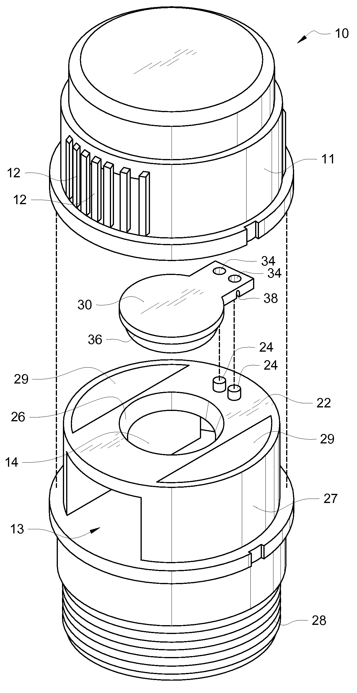
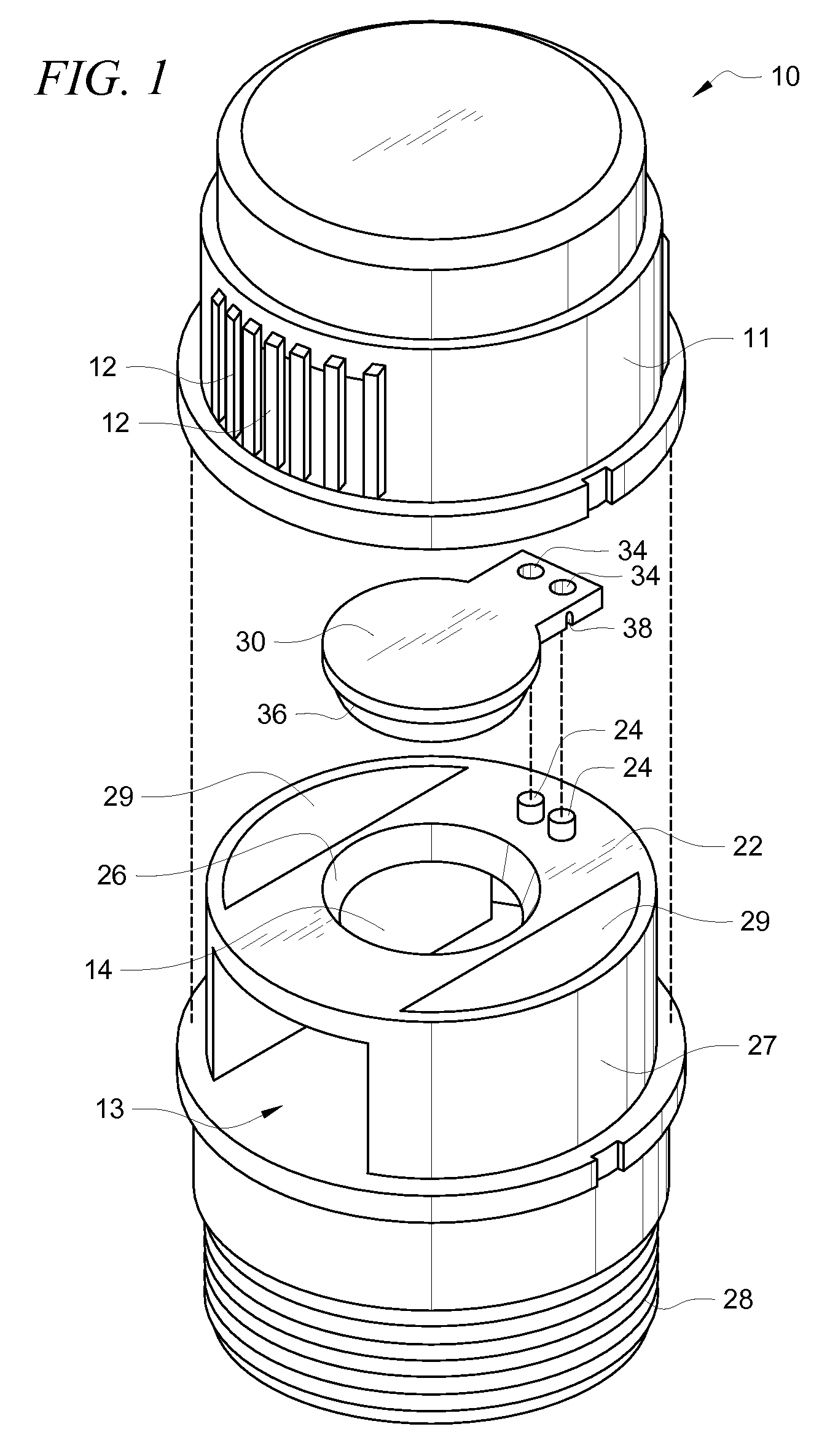
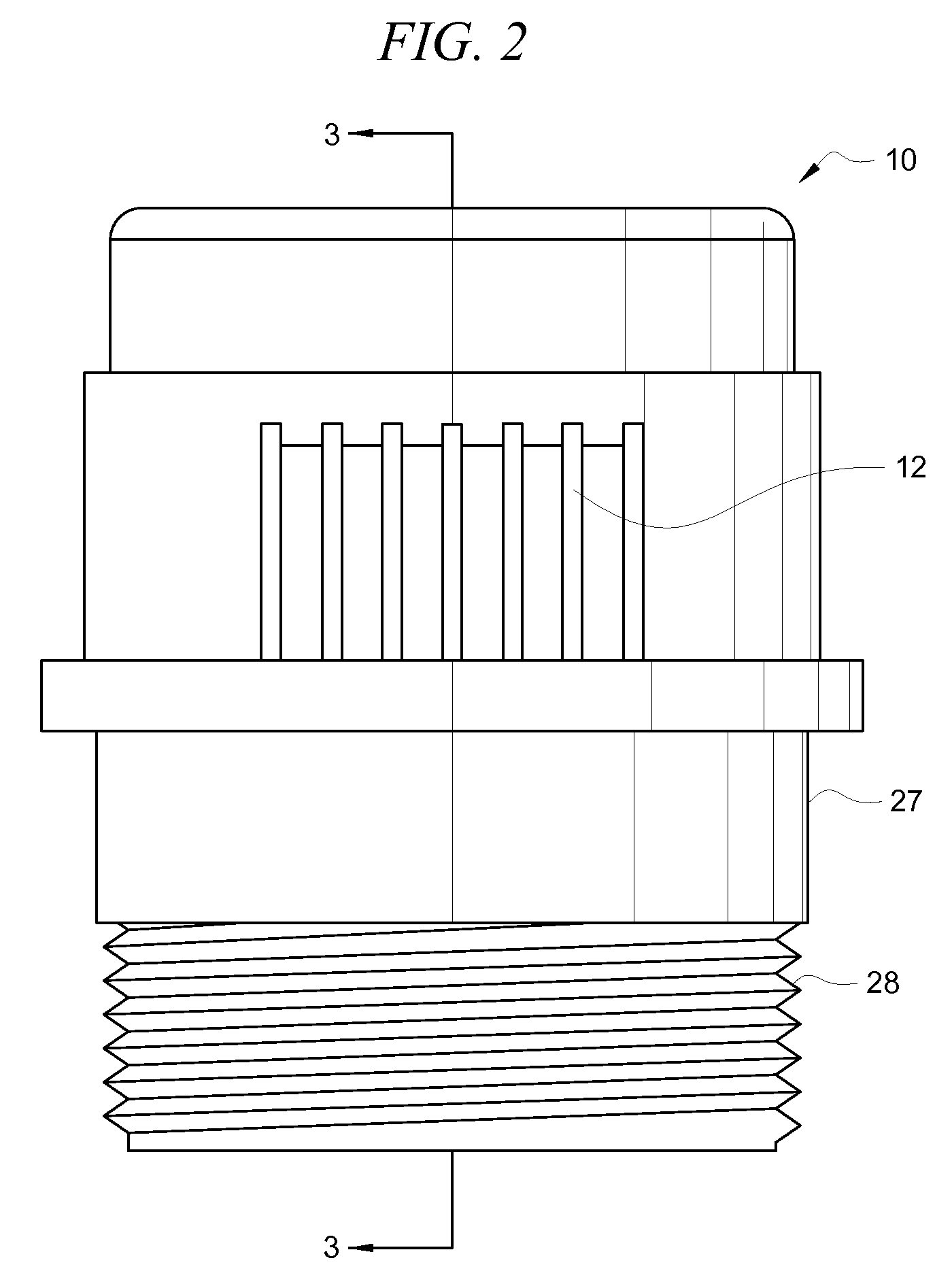
[0015]Referring to FIG. 1, an exploded view of the elements of the living-hinge valve air vent valve 10 will be described. The valve base 27 is shown with threads 28 for fastening to a sewer system conduit, for example, a PVC T-coupling with a threaded interface. In alternate embodiments, the valve base 27 has a non-threaded end having an outer diameter slightly smaller than the inner diameter of a standard sized PVC coupling such as a PVC T-coupling and the valve base 27 is glued to the PVC-T coupling as known in the industry (not shown).

[0016]The living-hinge valve air vent valve 10 has fluid connecting shafts 29 in fluid communication with the sewer system. When sewer gasses from the sewer system create ...


PUM


Abstract

An application for a living-hinge air vent valve connectable to a sewer conduit includes a base and a cover sealed to the base forming a cavity between the cover and the base. A fluid inlet shaft depends from a roof of the base and is connected to external air passages passing through a side of the base and through vents in a side of the cover. A living-hinge flapper is situated above the fluid inlet shaft and within the cavity. The living-hinge flapper allows air to flow from the fluid inlet shaft into the cavity and prevents sewerage gasses from flowing from the cavity out through the fluid inlet shaft. One or more connecting shafts in the base fluidly connect the cavity with a sewer system.

Description

FIELD OF THE INVENTION[0001]The present invention relates to air vent valves to relieve a vacuum developed in conduits. More particularly, it refers to a living-hinge valve for vacuum relief of domestic sewage piping systems in residential, commercial, industrial and institutional buildings.BACKGROUND OF THE INVENTION[0002]A single ball valve air vent is described in U.S. Pat. No. 6,234,198 to Chalich. Such a valve has received widespread commercial acceptance and is adequate to carry out its intended purpose. However, for large sewer pipes with drainage from multiple commodes a single air flow channel may not be adequate. For this reason the search continues for more efficient air flow in air vent valves.[0003]U.S. Pat. No. 7,140,388 to Chalich describes a dual ball valve air vent having two independent ball valves and providing multiple air flow channels.[0004]What is needed is an air vent valve that performs as well as the single or dual ball air valve vents but utilizes a living...

Claims


Application Information

Patent Timeline
IPC IPC(8): F16K15/03F16K17/18
CPCF16K15/031F16K15/03Y10T137/3294Y10T137/7897Y10T137/7898
Inventor CHALICH, WAYNE D.
Owner CHALICH WAYNE D
Why Eureka
Try Eureka