Method and System for Fluid Transmission along Significant Distances

a fluid transmission and significant distance technology, applied in the direction of insulated cables, transportation items, insulated conductors, etc., can solve the problems of increasing the pump pressure to increase the downstream fluid pressure, reducing the fluid pressure, and eventually becoming inconsequential,

Active Publication Date: 2009-03-19
SHOAP STEPHEN D
View PDF40 Cites 23 Cited by
  • Summary
  • Abstract
  • Description
  • Claims
  • Application Information

AI Technical Summary

Problems solved by technology

As a fluid is pumped through a hose or pipe, the fluid pressure drops as it gets farther from the pump, eventually becoming inconsequential.
Therefore, increasing pump pressure to increase downstream fluid pressure eventually becomes detrimental to the hose or pump.
Relay pumping is operationally challenging.
Several expensive fire trucks, which are often is short supply in various jurisdictions, must be dedicated to the relay operation and are thereby not available for other firefighting tasks.
This requires even more manpower and vehicles to transport fuels to the fire trucks.
In many wildfires, relay pumping cannot be implemented because large fire trucks or pump trucks cannot be driven off road into difficult terrain.
Special fire trucks that carry water tanks can go off road, but they can supply only a very limited quantity of water, inadequate for fighting most wildfires.
Irrigation canals require enormous amounts of earth moving, and they can suffer from excessive water loss due to evaporation.
However, pipelines require spatially distributed pumping stations to keep their fluids moving over long distances.
With tanker trucks, there are high transportation costs and a risk of vehicle accidents and fuel spills.
If three-phase power is not available on or near the farm, the cost to construct power lines may be prohibitive.
The cost and effort of delivering the diesel fuel to the diesel generators can be a burden.

Method used


Image

  • Method and System for Fluid Transmission along Significant Distances
  • Method and System for Fluid Transmission along Significant Distances
  • Method and System for Fluid Transmission along Significant Distances

Examples


Embodiment Construction

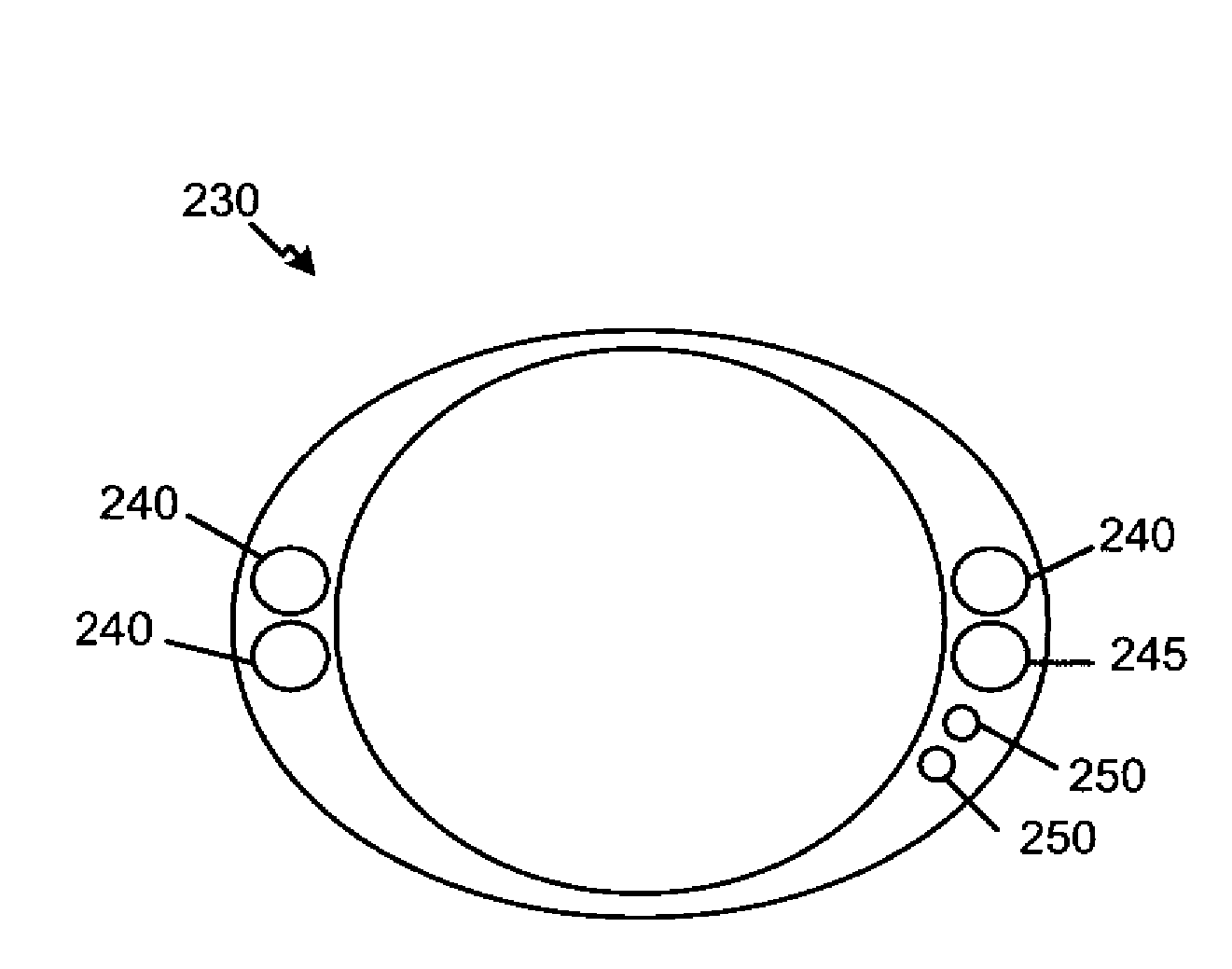
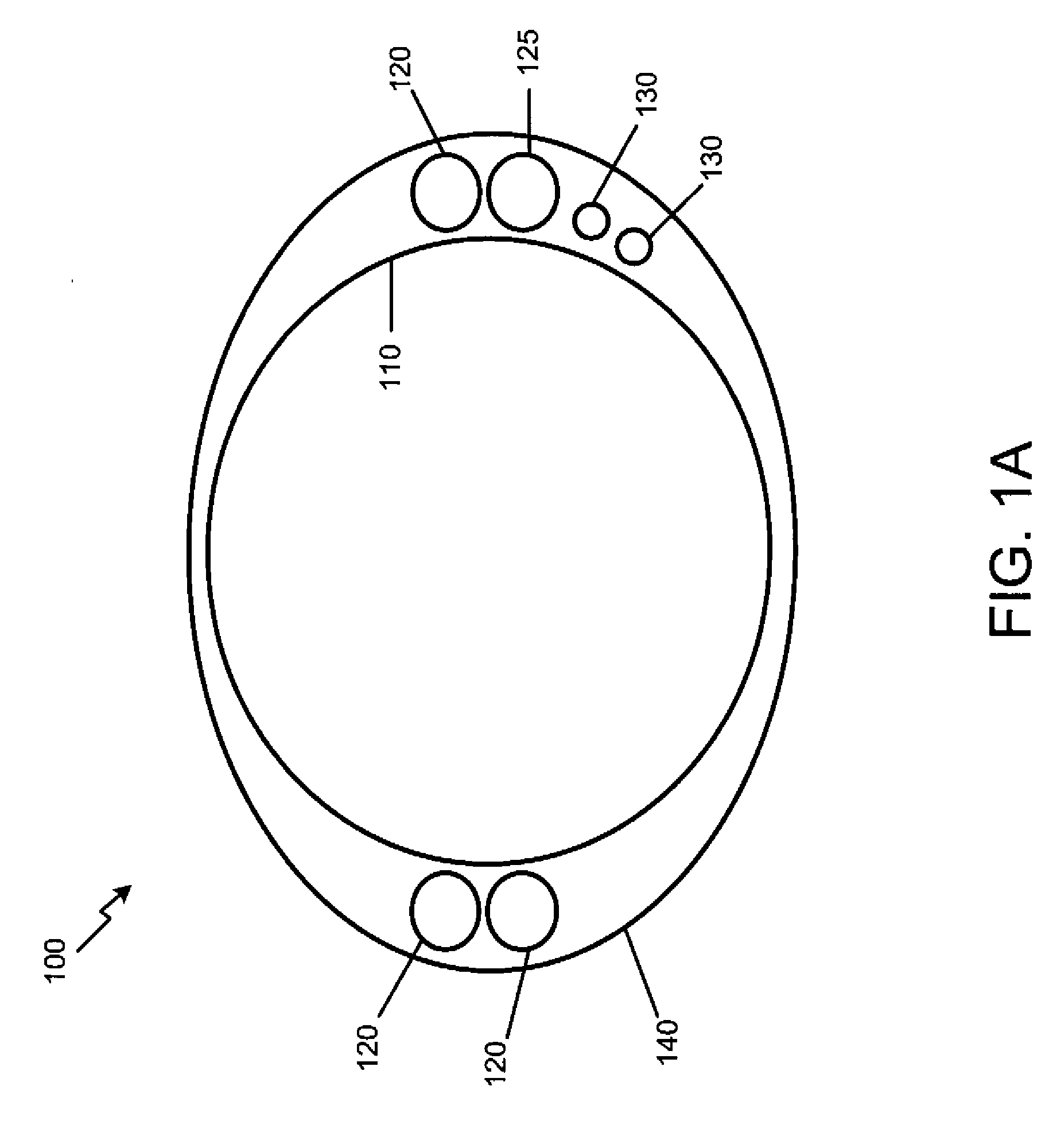
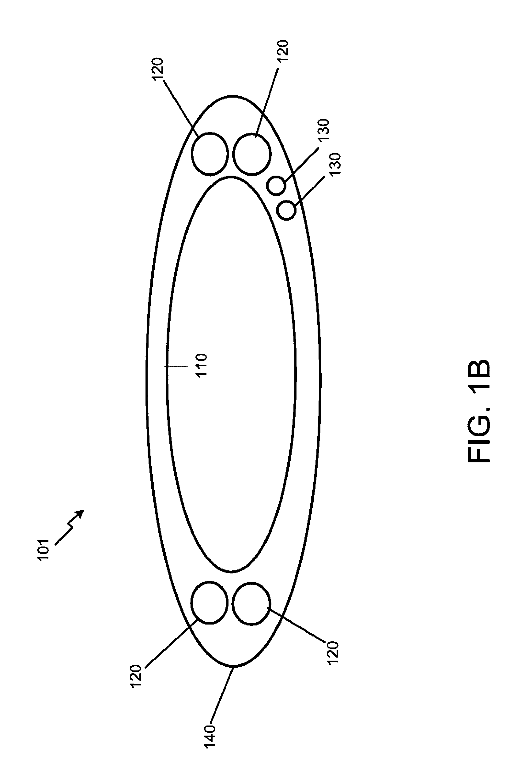
[0048]FIG. 1A is an illustration of a cross-section of a conduit, in accordance with a first exemplary embodiment of the present disclosure. FIG. 1A shows a cross section of a conduit, such as a fire hose or a rigid or semi-rigid pipe, combined with insulated electrical power wires 120 and communication wires 130, which will be referred to hereinafter as a wired fluid conduit (wfc) 100. The wired fluid conduit 100 can take the form of a wired fluid hose (wfh) 101, or a wired pipe (wp), each of which are defined by the material and characteristics of the conduit. FIG. 1A shows a cross-section of the wired fluid hose 101 when it is full of water and in its expanded mode. FIG. 1A also shows a cross-section of the rigid or semi-rigid wired pipe. Three power wires 120 supply three-phase electrical power and a fourth wire supplies a ground wire 125, although single-phase power may be similarly provided. The communication wires 130 may be used to support an Ethernet type of data network an...


PUM

PropertyMeasurementUnit
voltageaaaaaaaaaa
currentsaaaaaaaaaa
poweraaaaaaaaaa

Abstract

The system contains a plurality of conduit segments and at least one electrically-powered pump. At least one conduit connector joins the conduit segments and the electrically-powered pumps, thereby mating at least one fluid path. A plurality of electric power wires are coupled with the conduit segments and connected to the electrically-powered electric pumps. At least one electrical connector, within said conduit connectors, mates corresponding electric power wires between the conduit segments. An electric power source electrically connected to the electrically-powered pump via the electric power wires.

Description

CROSS-REFERENCE TO RELATED APPLICATION[0001]This application claims priority to copending U.S. Provisional Application entitled, “Some New Means for Moving Water and Fighting Wildfires” having Ser. No. 60 / 994,080 filed Sep. 17, 2007 and U.S. Provisional Application entitled “Further Inventions for Moving Water,” having Ser. No. 61 / 125,690, filed Apr. 28, 2008 which is entirely incorporated herein by reference.FIELD OF THE INVENTION[0002]This disclosure is in the field of electrical and fluid distribution. More specifically, this disclosure describes the use of electrical wires associated with fluid conduit.BACKGROUND OF THE INVENTION[0003]One related prior art device includes a pair of wires attached to a fire hose. The device allows a fireman at the output end of a hose to ring a bell at the fire truck. The bell is used to send simple signals to the fireman in control of the pumps sending water into the hose.[0004]Another prior art device is a grounding wire embedded in a fire hose...

Claims


Application Information

Patent Timeline
Patent Type & Authority Applications(United States)
IPC IPC(8): A62C31/00A62C33/00F16L11/12H01B7/42B05B15/68
CPCF16L11/12Y10T137/6899Y10T137/85978Y10T137/85994Y10T137/86139
Inventor SHOAP, STEPHEN D.
Owner SHOAP STEPHEN D
Why Eureka
Try Eureka