Hydraulic Elevator Stabilization Device

a technology of elevator stabilization and hydraulic pump, which is applied in the direction of elevators, transportation and packaging, etc., can solve the problems of low oil pressure from the pump and slow rotation, and achieve the effects of convenient testing and service, convenient operation, and convenient us

Inactive Publication Date: 2009-03-19
KRUCZKOWSKI RAFAL KAROL
View PDF0 Cites 0 Cited by
  • Summary
  • Abstract
  • Description
  • Claims
  • Application Information

AI Technical Summary

Benefits of technology

[0010]The presented device acts independent of any monitoring systems and includes its own braking mechanism. It should not be disengaged for any reason, as it only engages when the car accelerates beyond the predetermined speed. Once this speed is reached, further acceleration is limited and a car that before would have been in a sudden free fall, or rapid rise would simply raise or fall gently to the shaft's limit. This device is also easy in operation as it monitors and engages the brakes without the use of electricity, computer or magnets. In addition to ease of use, the system can be easily tested and serviced, as all components are centrally located.
[0011]The presented device can be easily mounted to almost all existing traction elevators and integrated with new elevator systems including; ski-lifts, cranes and other systems that utilize a traction spool that will accelerate rapidly in the event of a malfunction.
[0012]The device is composed of five core components. The brake system is mounted to the cable spool and anchored to the motor or some other solid object. The rotation of the cable spool rotates a gear box that adjusts the rotations to supply the pump with the proper speeds. The pump feeds the control box with high pressure oil. The control box monitors the incoming pressure and feeds it to the high pressure storage tank. When the pressure exceeds the calibrated pressure inside the control box, the excess is released to the brakes that engage on the rotor.

Problems solved by technology

Normal operation of the elevator will result in slow rotations from the gearbox, thus low oil pressure from the pump.

Method used


Image

  • Hydraulic Elevator Stabilization Device
  • Hydraulic Elevator Stabilization Device
  • Hydraulic Elevator Stabilization Device

Examples


Embodiment Construction

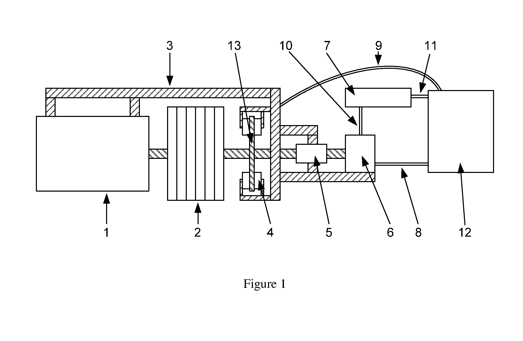
[0015]Unit 1 is the motor, optionally including a transmission that powers the cable spool.

Unit 2 is the cable spool.

Unit 3 is the supporting frame that anchors the brakes and pump.

Unit 4 is the brakes that engage on the rotor.

Unit 5 is the transmission that changes the rotation speed to accommodate the pump.

Unit 6 is the pump that feeds high pressure oil depending on the rotating speed of the cable spool.

Unit 7 is the high-pressure oil storage tank.

Unit 8 is a high-pressure pipe that feeds oil to the control box.

Unit 9 is a high-pressure hose that feeds pressure to the bakes.

Unit 10 is a high pressure pipe that feeds oil to the pump.

Unit 11 is a high pressure oil pipe that feeds oil to the tank.

Unit 12 is the control box that monitors the incoming pressure from the pump.

Unit 13 is the rotor that rotates with the cable spool.

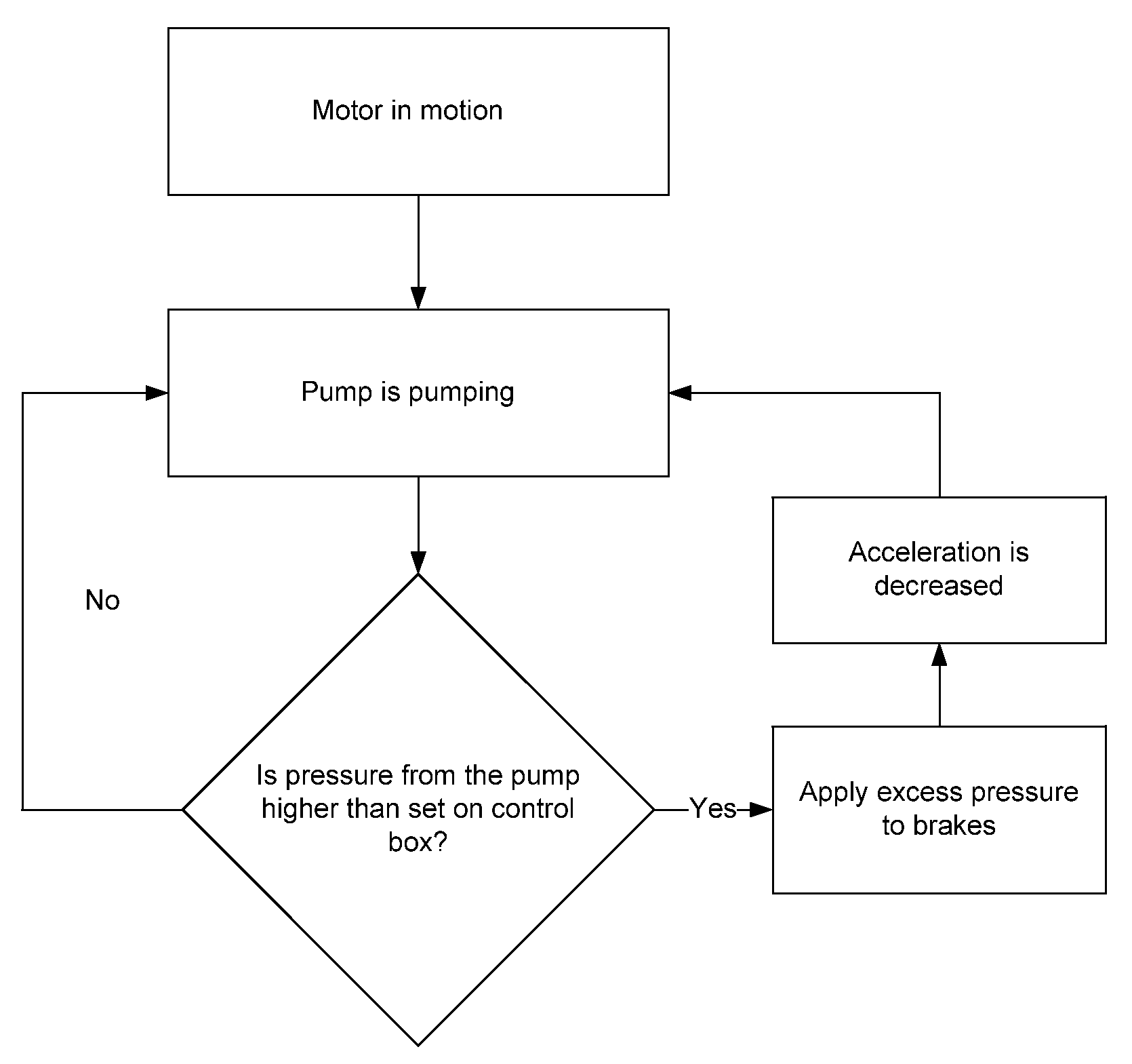
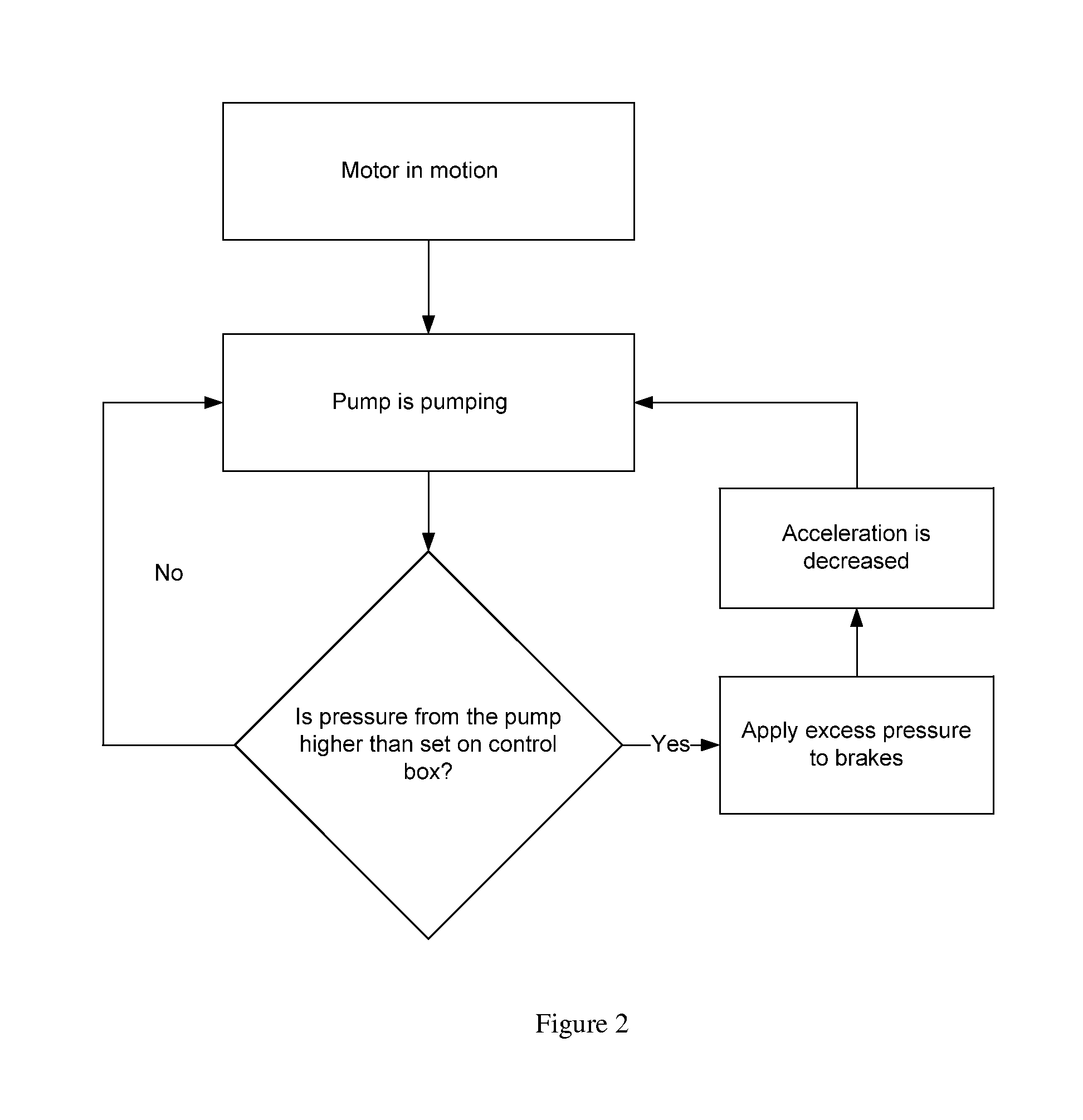
OPERATION OF INVENTION

[0016]There is no need for cables, electricity or computer to operate the device. At the end of the traction sheave, a rotor-based braking...


PUM


Abstract

The invented device works by attaching a rotor brake to the traction sheave while anchored to a solid object. When the traction sheave is rotating at normal speeds, the hydraulic pump maintains a consistent oil pressure in the storage tank. In the event of a sudden acceleration in either direction, the control box valve overflows the excess pressure and apples it to the rotor brakes, slowing the movement of the car and stabilizing the traction sheave in addition of the cargo and occupants.

Description

CROSS REFERENCE TO RELATED APPLICATIONS[0001]USPTO U.S. Pat. No. 815,629 Emergency Brake for ElevatorsUSPTO U.S. Pat. No. 4,531,617 Overspeed Safety Braking DeviceUSPTO U.S. Pat. No. 4,923,055 Safety Mechanism for Preventing Unintended Motion in Traction ElevatorsDE 20207996 TreibscheibenbremseSTATEMENT REGARDING FEDERALLY SPONSORED RESEARCH OR DEVELOPMENT[0002]The presented patent is not sponsored or funded by the US or any other government.REFERENCE TO SEQUENCE LISTING, A TABLE, OR A COMPUTER PROGRAM LISTING COMPACT DISC APPENDIX[0003]Not ApplicableBACKGROUND OF THE INVENTION[0004]Modern elevators employ various safety devices that will quickly halt the passenger car in the event of a system malfunction. Current systems that are employed on elevators include brakes that are mounted on the car, and along the cable from above. These systems have been proven to work, but when they engage the cabin comes to a sudden halt that may injure passengers, or damage cargo.[0005]Another common...

Claims


Application Information

Patent Timeline
Patent Type & Authority Applications(United States)
IPC IPC(8): B66B1/32
CPCB66B5/028
Inventor KRUCZKOWSKI, RAFAL KAROL
Owner KRUCZKOWSKI RAFAL KAROL
Why Eureka
Try Eureka