Eureka AIR delivers breakthrough ideas for toughest innovation challenges, trusted by R&D personnel around the world.

Magnetorheological (MR) piston, MR piston assembly, and MR damper system

Active Publication Date: 2009-03-19
DELPHI TECH INC +1
View PDF6 Cites 58 Cited by
  • Summary
  • Abstract
  • Description
  • Claims
  • Application Information

AI Technical Summary

Benefits of technology

[0005]A first expression of an embodiment of the invention is for a magnetorheological (MR) piston assembly including an MR piston and a rod. The MR piston includes a central longitudinal axis, first and second longitudinal ends, an MR passageway, a main electric coil, and a valve. The MR passageway extends from the first longitudinal end to the second longitudinal end. The

Problems solved by technology

A disruption of electric power (from whatever cause) will terminate power to the electromagnetic-valve coil and cause the valve to restrict the MR passageway resulting in firm damping.

Method used


Image

  • Magnetorheological (MR) piston, MR piston assembly, and MR damper system
  • Magnetorheological (MR) piston, MR piston assembly, and MR damper system
  • Magnetorheological (MR) piston, MR piston assembly, and MR damper system

Examples


Embodiment Construction

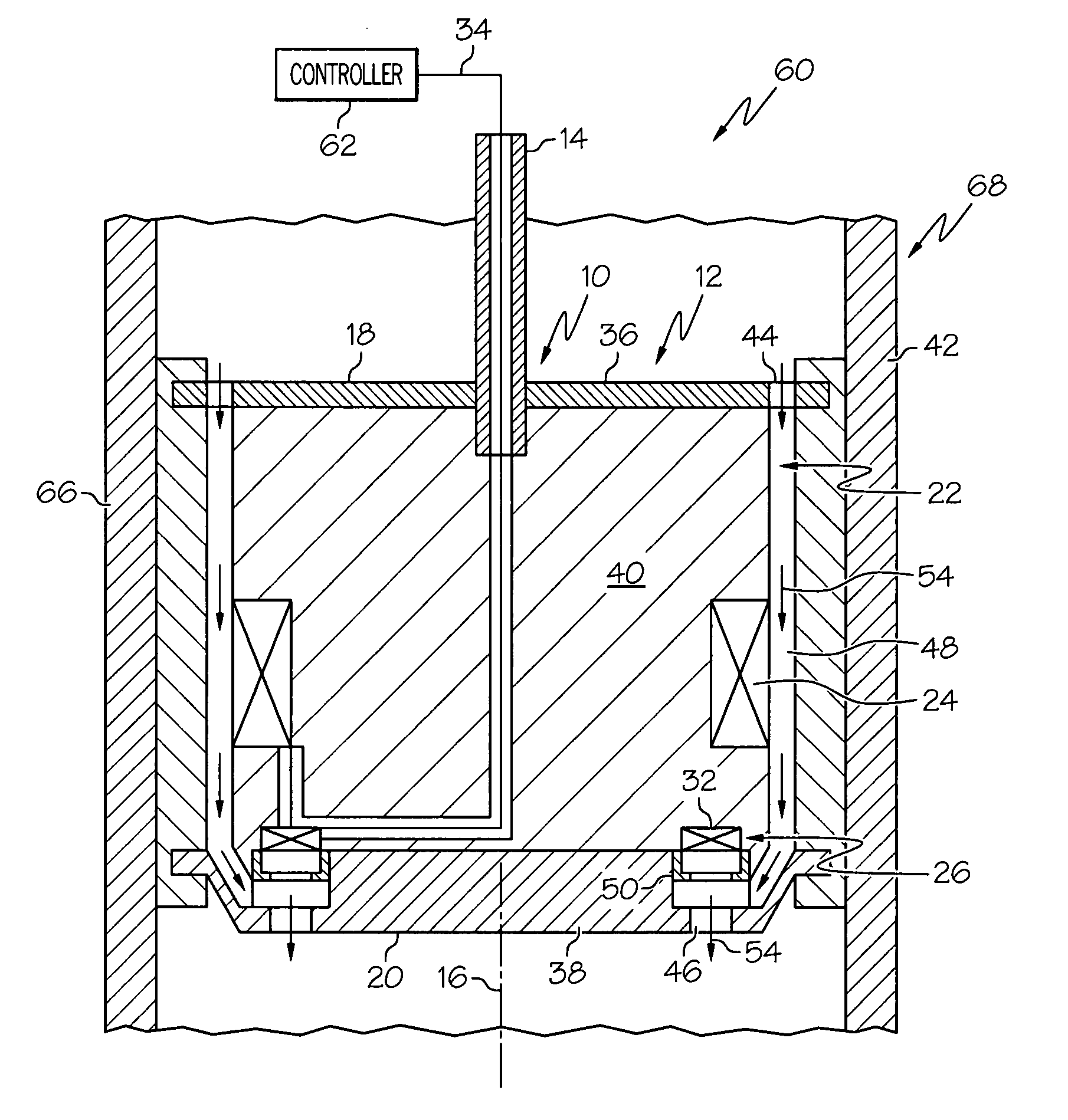
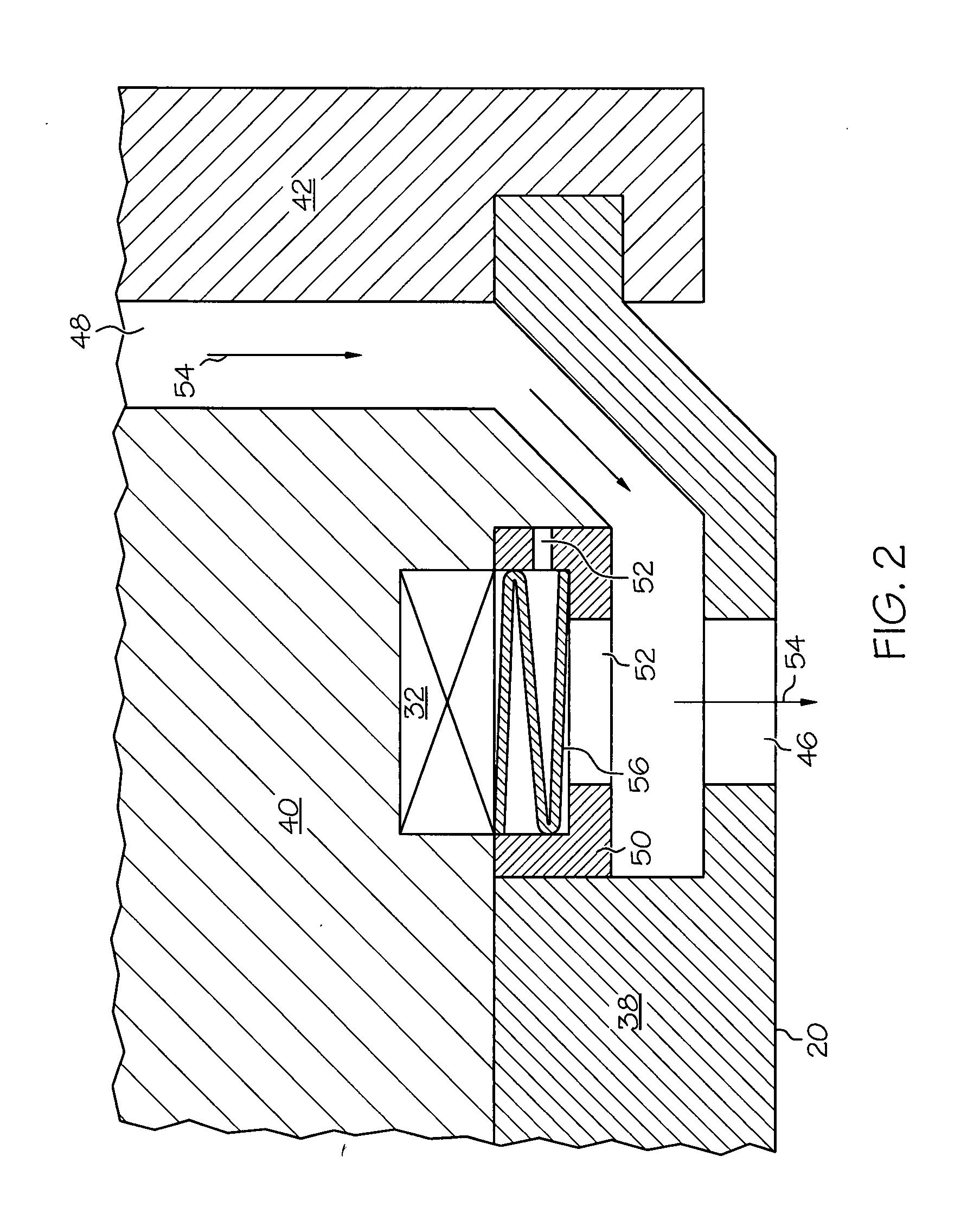
[0014]It is noted that like parts are numbered alike throughout the figures. Referring now to the drawings, FIGS. 1-5 show an embodiment of the present invention. A first expression of the embodiment of FIGS. 1-5 is for a magnetorheological (MR) piston assembly 10 including an MR piston 12 and a rod 14. The MR piston 12 includes a central longitudinal axis 16, first and second longitudinal ends 18 and 20, an MR passageway 22, a main electric coil 24, and a valve (such as, but not limited to an electromagnetic valve 26). The MR passageway 22 extends from the first longitudinal end 18 to the second longitudinal end 20. The main electric coil 24 is disposed to magnetically energize the MR passageway 22. The valve (e.g., 26) is operatively connected to the MR passageway 22. The valve (e.g., 26) has a first state when electrically activated which is less restrictive of the MR passageway 22 and has a second state when not electrically activated (from whatever cause) which is more restrict...


PUM


Abstract

A magnetorheological (MR) piston assembly (10) includes an MR piston (12) and a rod (14). The MR piston (12) includes a central longitudinal axis (16), first and second longitudinal ends (18 and 20), an MR passageway (22), a main electric coil (24), and a valve (26). The MR passageway (22) extends from the first longitudinal end (18) to the second longitudinal end (20). The main electric coil (24) is disposed to magnetically energize the MR passageway (22). The valve (26) is operatively connected to the MR passageway (22). The valve (26) has a first state when electrically activated which is less restrictive of the MR passageway (22) and has a second state when not electrically activated which is more restrictive of the MR passageway (22). The rod (14) is attached to the MR piston (12). A more detailed MR piston (12) and an MR damper system (60) are also described.

Description

TECHNICAL FIELD[0001]The present invention relates generally to piston dampers, and more particularly to a magnetorheological (MR) piston, to an MR piston assembly, and to an MR damper system.BACKGROUND OF THE INVENTION[0002]Conventional piston dampers include MR dampers having a tube containing an MR fluid and having an MR piston assembly including a piston which slideably engages the tube and including a rod which has a first end attached to the piston and a second end extending outside the tube. The MR fluid passes through an MR passageway (i.e., a magnetically energizable passageway) of the MR piston. Exposing the MR fluid in the MR passageway to a varying magnetic field, generated by providing a varying electric current from a controller to an electric coil of the MR piston, varies the damping effect of the MR fluid in the MR passageway providing variably-controlled damping of relative motion between the MR piston and the tube. The electric current is varied (including turning ...

Claims


Application Information

Patent Timeline
IPC IPC(8): F16F9/53F16F9/34
CPCF16F9/537
Inventor LUN, SAIMAN
Owner DELPHI TECH INC
Why Eureka
Eureka Blog
Learn More