Conveyor system aligner and method of aligning

Active Publication Date: 2009-03-19
DEMATIC
View PDF15 Cites 5 Cited by
  • Summary
  • Abstract
  • Description
  • Claims
  • Application Information

AI Technical Summary

Benefits of technology

[0004]The present invention is directed to a conveyor system aligner and method of aligning

Problems solved by technology

Certain known carton aligners have been difficult to maintain and subject to excessive wear.
Because both belts should travel at close to the same speed, which is

Method used


Image

  • Conveyor system aligner and method of aligning
  • Conveyor system aligner and method of aligning
  • Conveyor system aligner and method of aligning

Examples


Example

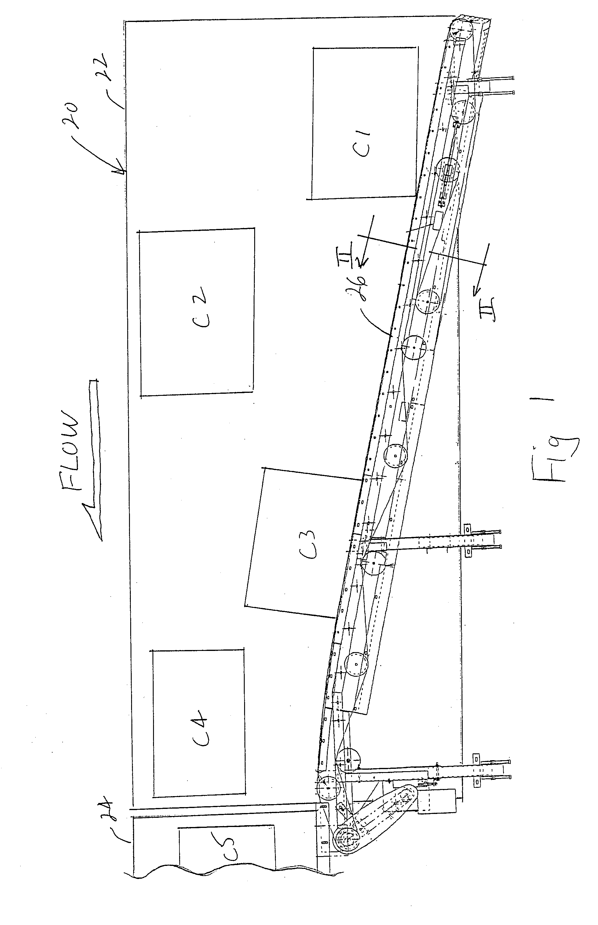
[0019]Referring now specifically to the drawings, and the illustrative embodiments depicted therein, a conveyor system 20 includes a conveying belt 22 which may be fed items or articles, such as cartons, or the like, from two or more feed lines (not shown) and which discharges articles to a takeaway conveyor 24 for feeding in a singulated manner to a downstream process, such as a sortation system, or the like (FIG. 1). An aligner assembly 26 displaces articles, such as cartons C1 and C3 illustrated in FIG. 1, that come into contact with the aligner assembly in order to align the articles in a single file with other cartons, such as cartons C2 and C4, that do not contact the aligner assembly.

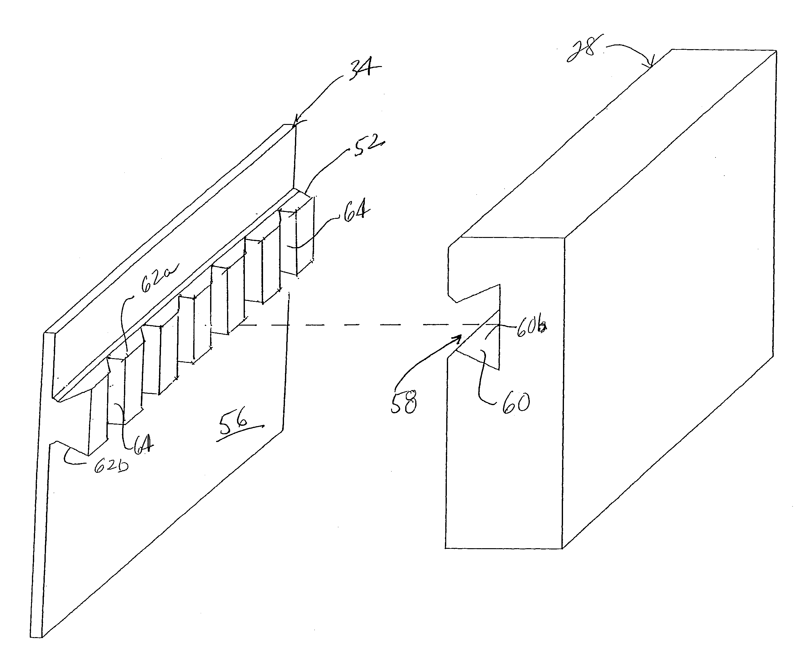
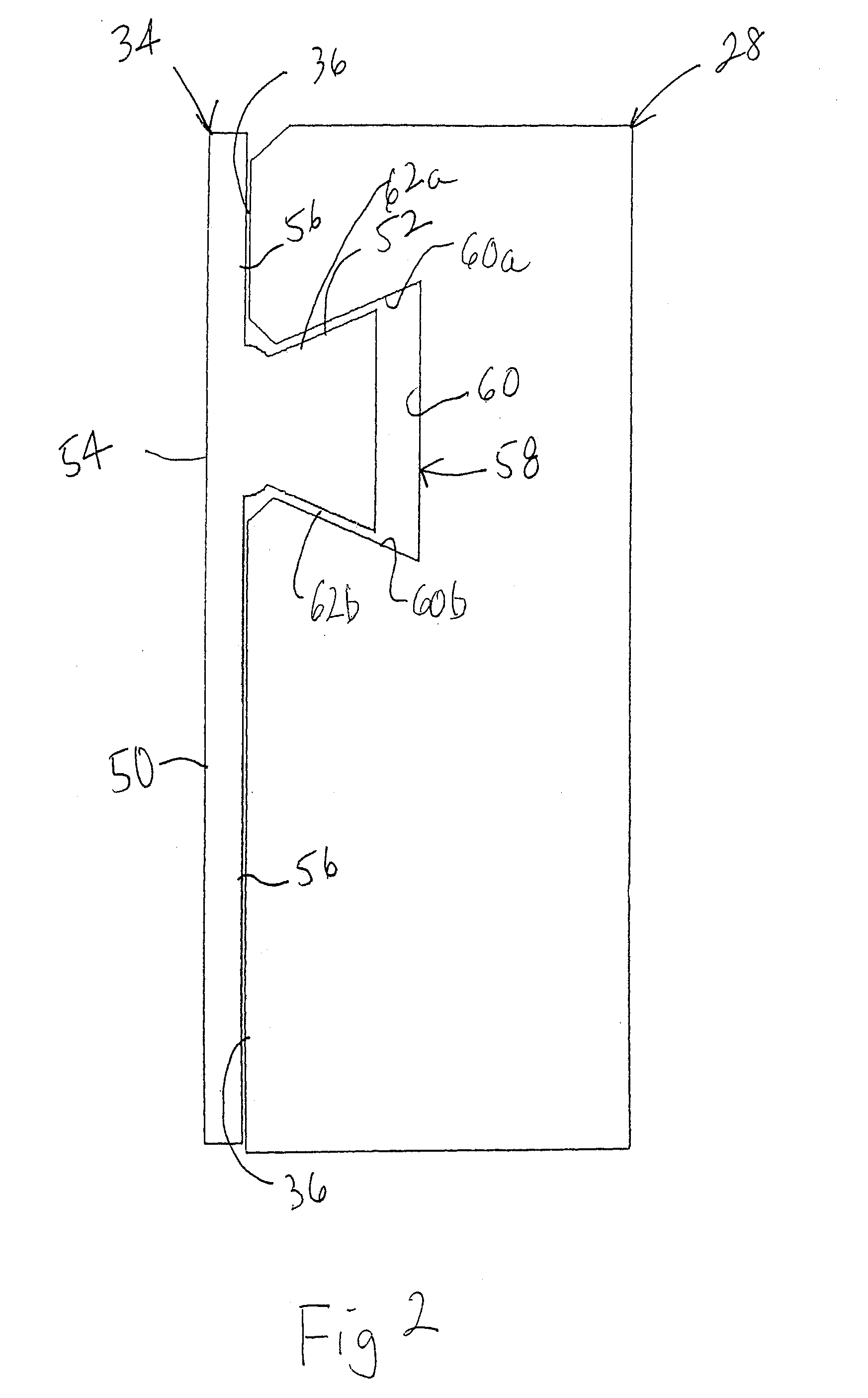
[0020]Alignment assembly 26 includes a belt support assembly 28 mounted by a frame 30 supported by frame support members 32 (FIG. 5). Alignment assembly 26 additionally includes a vertically oriented continuous aligning belt 34 that engages a generally vertical support surface 36 of a belt suppor...


PUM


Abstract

A conveyor system aligner, method of aligning and continuous aligning belt includes providing a belt support assembly having a generally vertical support surface and a channel defined in the support surface. A belt drive propels the aligning belt along the support surface and items, such as cartons, are conveyed past the aligning belt. A continuous aligning belt is provided that has a contact portion and a guide member. The contact portion has a contact surface and a glide surface. The glide surface is configured to travel along the support surface. The guide member is adapted to be captured by the channel and travels in the channel to support the aligning belt.

Description

CROSS REFERENCE TO RELATED APPLICATION[0001]This application claims priority from U.S. provisional patent application Ser. No. 60 / 973,577 filed on Sep. 19, 2007, the disclosure of which is hereby incorporated herein by reference in its entirety.BACKGROUND OF THE INVENTION[0002]The present invention is directed to a conveyor system carton aligner and method of aligning cartons and, in particular, to a technique for aligning articles, such as cartons, into a single file.[0003]Certain known carton aligners have been difficult to maintain and subject to excessive wear. In one such carton aligner, a pair of vertically spaced driven circular belts travel in circular channels with a portion of each belt extending outside the channel to be contacted by cartons in order to align the cartons along the face of the assembly. Each of the belts is reeved by its own system of sheaves and driven by its own belt drive. In order to replace the lower belt, the upper belt must be removed and replaced. ...

Claims


Application Information

Patent Timeline
IPC IPC(8): B65G21/20
CPCB65G21/2054B65G2201/025B65G47/22
Inventor WOLF, STEPHEN C.
Owner DEMATIC
Why Eureka
Try Eureka