Movement and power generation apparatus

a technology of power generation apparatus and moving parts, applied in electrical equipment, control systems, sea energy generation, etc., can solve the problems of non-use, environmental protection, and unfriendly utilization of the same, and achieve the effect of eliminating any gearbox drag

Inactive Publication Date: 2009-03-19
MCCAGUE JAMES +1
View PDF17 Cites 52 Cited by
  • Summary
  • Abstract
  • Description
  • Claims
  • Application Information

AI Technical Summary

Benefits of technology

[0031]Typically, when the first member rises under the influence of the body of water, the one or more unidirectional clutches connected to the wave upward movement engage and the gearbox will come under load and increase the shaft revolutions thereby driving a fly wheel and subsequently the electrical power generator. On another of the rotatable means, on the gravity or wave downward side of the member, at this time the unidirectional clutch or clutches connected thereto, will freewheel and therefore the gravitational gearbox need never be reversed. This freewheeling therefore eliminates any gearbox drag from slowing the flywheel and ultimately the electrical generator connected thereto.
[0032]When the wave reverses, i.e. the first member and second member move downwardly the one or more unidirectional clutches on the gravity driven side will engage and therefore the gearbox will come under load and increase the shaft revolutions, therefore driving the flywheel and therefore the gravity electrical generator. The wave upward driven side rotatable means will rotate in an opposite direction and the unidirectional clutch connected thereto will freewheel, therefore the gravitational gearbox need never be reversed and the unidirectional clutch between the gearbox and flywheel will freewheel therefore eliminating any gearbox drag from slowing the flywheel and ultimately the electrical generator.

Problems solved by technology

The provision of electricity power generation is conventionally by the burning of oil, gas or coal fuels which causes the depletion of non-renewable resources and is environmentally unfriendly.
One form is nuclear power generation but this has well known disadvantages and therefore there is resistance to utilization of the same.
The use of natural resources is another option and the use of solar generation, wind power and sea power, is known but, at the present time, is performed on a relatively small scale and each have their own inherent problems.

Method used


Image

  • Movement and power generation apparatus
  • Movement and power generation apparatus
  • Movement and power generation apparatus

Examples


Embodiment Construction

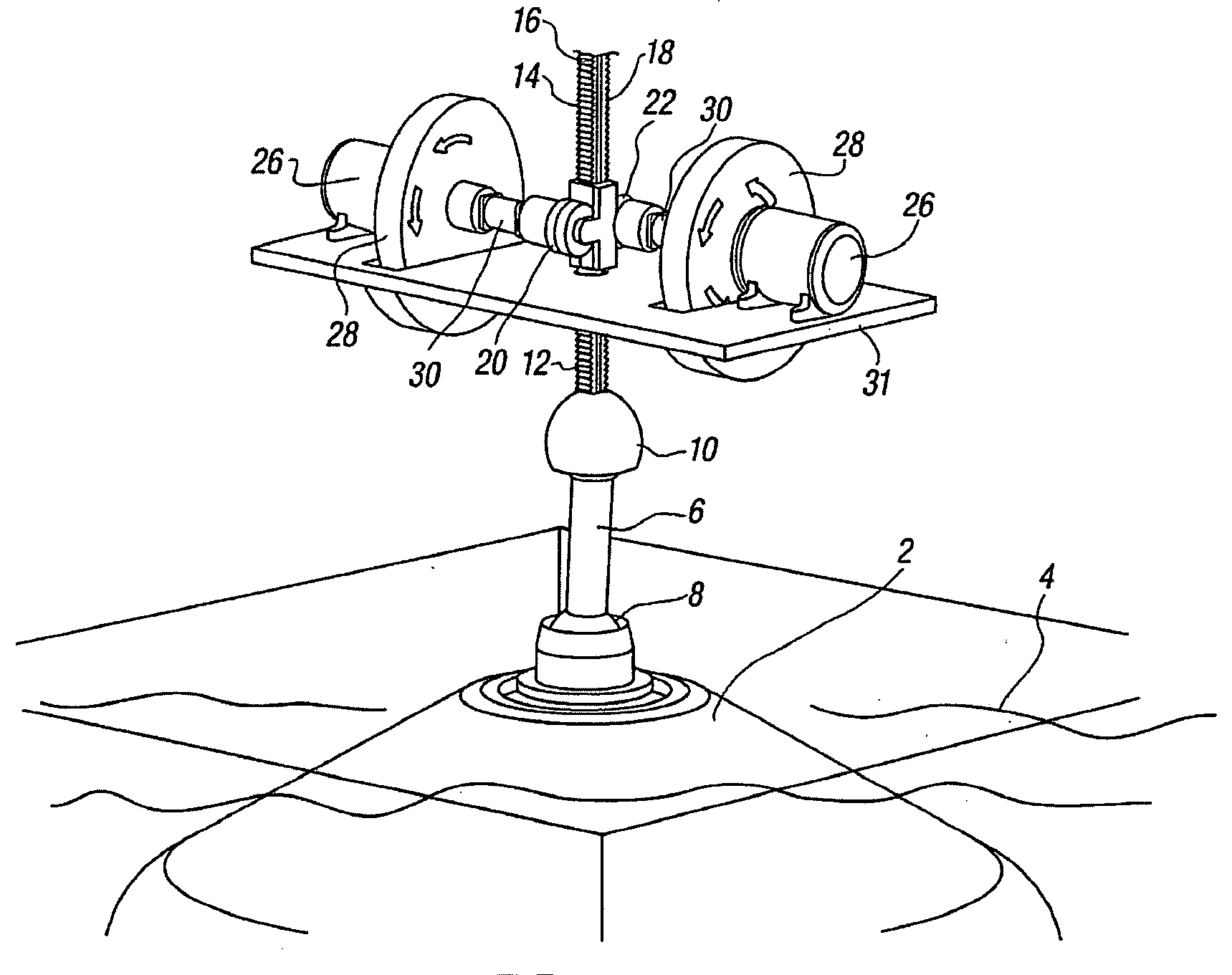
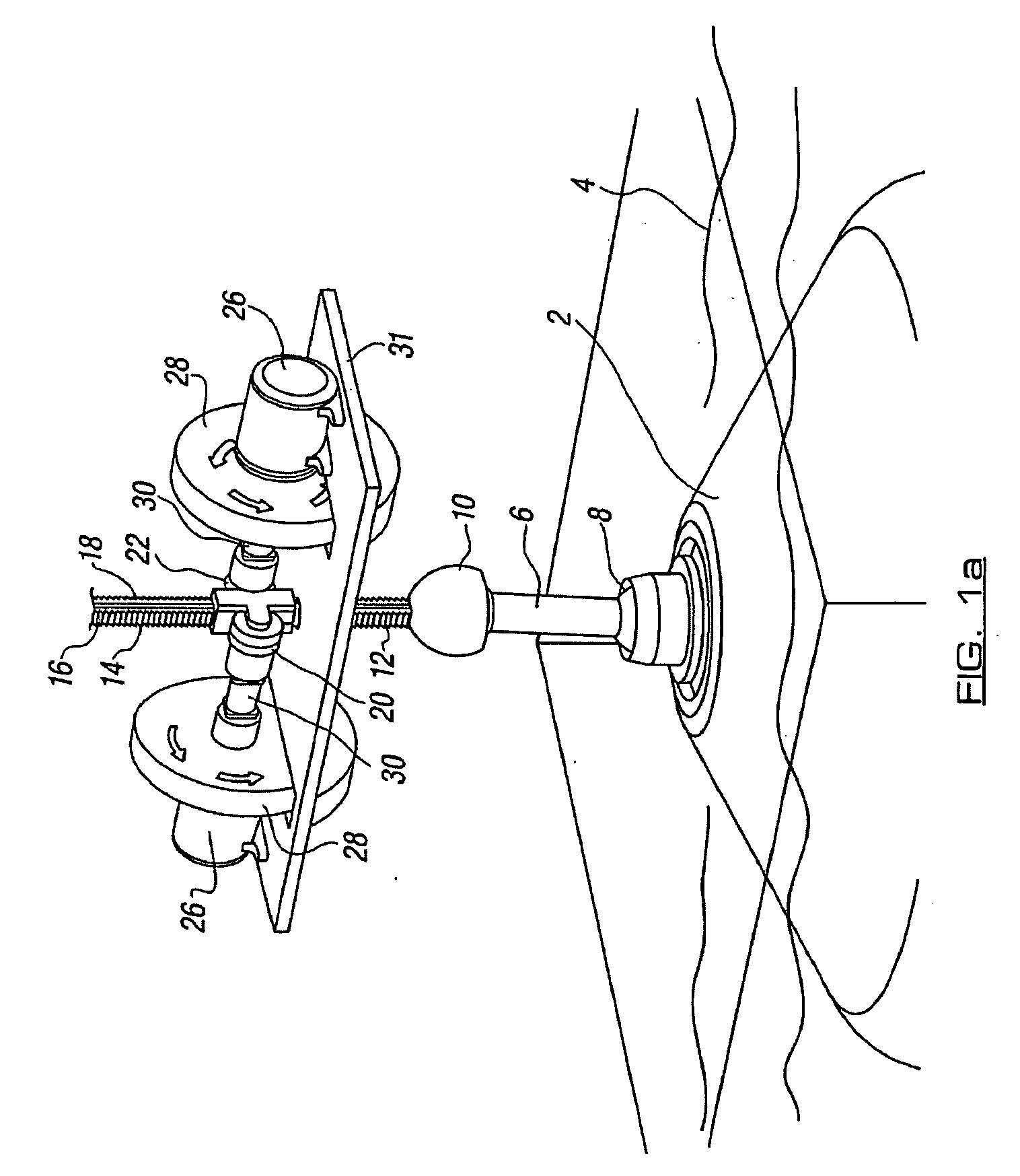
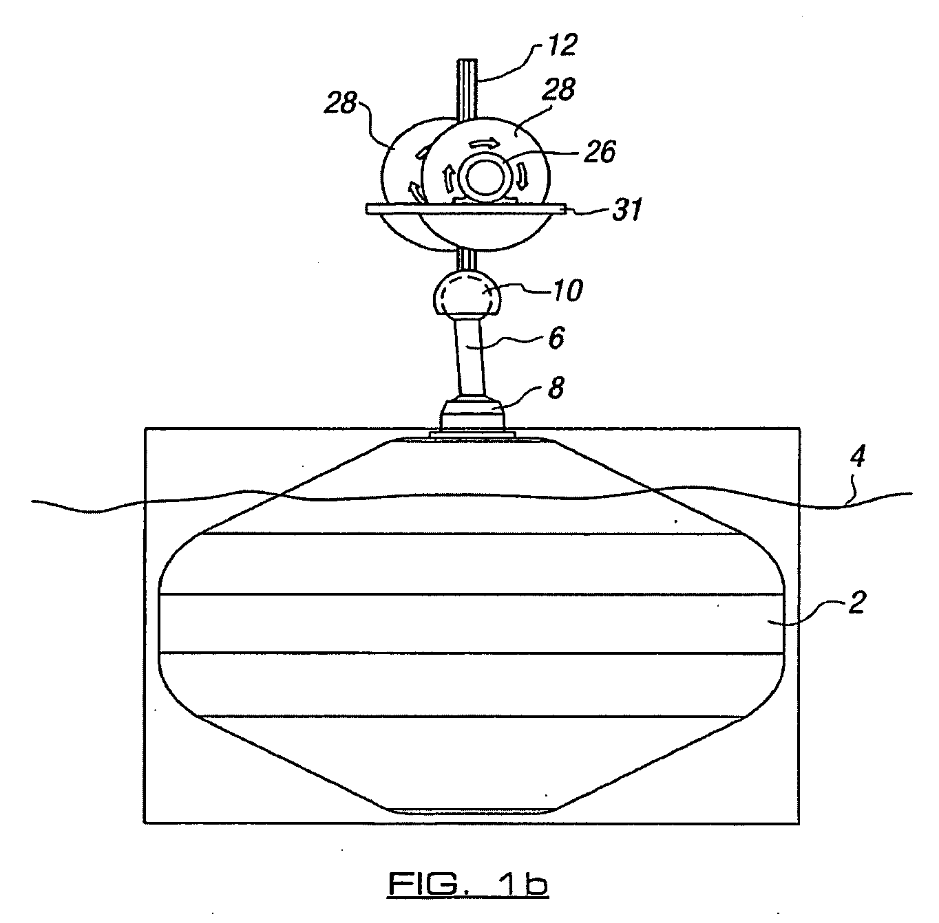
[0050]Referring firstly to FIGS. 1a to 1c, there is illustrated apparatus in accordance with one embodiment of the invention. In this case, the apparatus comprises a first member in the form of a float 2 which is provided to lie at or adjacent to the surface of a body of water 4, as shown. The preferred arrangement of the first member will be described subsequently. The first member is connected to the remainder of the apparatus by a connector assembly 6 which comprises a first universal joint 8 and a second universal joint 10. The second universal joint 10 is connected in turn to a second member of the apparatus 12. The second member, in this embodiment, is formed as a double-sided rack with teeth 14 provided on opposing sides 16 and 18 and along the length thereof. Rotatable means, in the form of pinions 20, 22 are provided for each of the racks and mesh with the teeth thereon. Each of the rotatable means is connected to a power generator 26 via a flywheel 28 and gearing mechanism...


PUM


Abstract

The invention relates to apparatus which allows the movement of a body of water, such as that created by waves and/or a swell in the sea, to be utilized to generate power. The apparatus includes a first member in the form of a float, which is connected to a second member and at least one rotatable means connected to a power generator. In one embodiment the second member is connected with and supported on the first member while the rotatable member and power generator are provided at a relatively fixed location and coupled to second member such that relative movement of the second member with respect to the rotatable means is used to cause the generation of power.

Description

CROSS REFERENCE TO RELATED APPLICATIONS[0001]This application is a continuation of PCT Application No. PCT / GB2007 / 001498, filed Apr. 24, 2007, which claims benefit of Great Britain Application No. GB0608128.5, filed Apr. 25, 2006.FIELD OF THE INVENTION[0002]The invention to which this application relates is to apparatus which can be used to harness movement of a body of water in at least a first direction and allow the transmission of said movement into a second form of movement which is more useful for a specified purpose such as, but not necessarily exclusively, to allow power generation.SUMMARY OF THE INVENTION[0003]In particular, although again not necessarily exclusively, the apparatus is for use in respect to first movement as a linear component of movement of the body of water and the said movement is translated into a second, rotational, movement. The apparatus is herein described with regard to movement of a body of water such as the sea and the transmission of the said mov...

Claims


Application Information

Patent Timeline
Patent Type & Authority Applications(United States)
IPC IPC(8): F03B13/12
CPCF03B13/186Y02E10/38F05B2240/40Y02E10/30
Inventor MCCAGUE, JAMESCONDRY, SIMON
Owner MCCAGUE JAMES
Why Eureka
Try Eureka