
Casting roll

a technology of casting roll and roll body, which is applied in the field of casting roll, can solve the problems of strip fracture and reduction in cooling efficiency, and achieve the effects of effective cooling the outer periphery, enhancing the revolution of the roll body, and enhancing the production efficiency of strip

Inactive Publication Date: 2010-05-06
IHI CORP
View PDF3 Cites 0 Cited by
  • Summary
  • Abstract
  • Description
  • Claims
  • Application Information

AI Technical Summary

Benefits of technology

[0027]A casting roll according to the invention can exhibit the following effects and advantages.
[0028](1) In either of the first and second aspects of the invention, the longitudinal cooling passages pass through the roll body from one end of the roll on which one of the side weirs abuts to the other end of the roll on which the other side weir abuts, so that the distance can be reduced between the longitudinal cooling passages and the outer periphery of the roll body to effectively cool the outer periphery of the roll body.
[0029](2) In either of the first and second aspects of the invention, the cooling water is directly in contact with the plugs and the end inner peripheries of the longitudinal cooling passages, so that end vicinities of the outer periphery of the roll body can be more effectively cooled.
[0030](3) In the first aspect of the invention, the plugs fitted into the ends of the longitudinal cooling passages are held by the sleeve and flange of the stub axle. As a result, even if the plugs are reduced in size axially of the roll, the plugs are not deformed by the pressure of the cooling water, the cooling water being prevented from leaking.
[0031](4) In the second aspect of the invention, the plugs fitted into the ends of the longitudinal cooling passages are held by the flange of the stub axle. As a result, even if the plugs are reduced in size axially of the roll, the plugs are not deformed by the pressure of the cooling water, the cooling water being prevented from leaking.
[0032](5) In either of the first and second aspects of the invention, the outer periphery of the roll body can be satisfactorily cooled. As a result, for example, the revolution of the roll body can be enhanced to enhance production efficiency of strip. If there is no need of enhancing the revolution of the roll body, the flow rate of the cooling water may be reduced, which contributes to simplification of ancillary facilities such as pump, piping or cooler and thus reduction in pumping power.

Problems solved by technology

Any solidified shell produced at the triple point region may be dragged and peeled by the solidified shell formed on the outer periphery of the roll body 2 and may be bitten at the nip, which brings about not only defective shape of the locally thickened strip S but also flaring or expansion of the nip due to the defective portion of the strip, resulting in reduction in cooling efficiency, fracture of the strip S due to reheating from the molten metal and damage on the side weirs 1 upon drop-out of the solidified shell.

Method used


Image

  • Casting roll
  • Casting roll
  • Casting roll

Examples


first embodiment

[0057]FIGS. 3 and 4 show a continuous casting machine with casting rolls of the invention. Each of the casting rolls comprises a cylindrical roll body 12 with axial ends having marginal portions on which side weirs 11 abut, short tube-shaped supports 13 each coaxially protruding from the roll body 12, a stub axle 14 fitted into the support 13, a sleeve 15 fitted over the support 13 and a flange 16 contiguous with the stub axle 14 and abutting on the sleeve 15 on a side away from the roll body 12.

[0058]The roll body 12 is formed with longitudinal cooling passages 17 passing through the roll from one end of the roll to the other end of the roll and radial cooling passages 18 each located near a corresponding end of the roll and passing from an inner periphery of the roll to a corresponding longitudinal cooling passage 17.

[0059]The longitudinal cooling passages 17 are located circumferentially equidistantly of the roll body 12 and the radial cooling passages 18 extend radially of an ax...

second embodiment

[0074]FIGS. 5 and 6 show a continuous casting machine with casting rolls according to the invention. Each of the casting roll comprises a cylindrical roll body 24 with axial end marginal portions on which side weirs 23 abut, stub axles 25 each fitted into the roll body 24 and a flange 26 contiguous with the stub axle 25 and facing to the corresponding end of the roll body 24.

[0075]The roll body 24 is formed with longitudinal cooling passages 27 passing from one end to the other end of the roll and radial cooling passages 28 each located near a corresponding end of the roll and leading from an inner periphery of the roll to a corresponding longitudinal cooling passage 27.

[0076]The longitudinal cooling passages 27 are located circumferentially equidistantly of the roll body 24 and the radial cooling passages 28 extend radially of an axis of the roll body 24.

[0077]Further, fitted into each end of the longitudinal cooling passages 27 is a disk-like plug 29 so as to abut on the flange 26...


PUM

PropertyMeasurementUnit
thicknessaaaaaaaaaa
outer diameteraaaaaaaaaa
diameteraaaaaaaaaa

Abstract

Intended is to provide a casting roll having an outer periphery capable of being efficiently cooled.The casting roll has a roll body on which side weirs 11 abut, short tube-shaped supports 13 each coaxially with and protruding from the roll body 12, a stub axle 14 fitted into the support 13, a sleeve 15 fitted over the support 13 and a flange 16 contiguous with the stub axle 14 and abutting on the sleeve 15 on a side away from the roll body 12. The roll body 12 is formed with longitudinal cooling passages 17 passing through the roll from one end to the other end of the roll as well as radial cooling passages 18 each adjacent to a corresponding end of the roll and extending from an inner periphery of the roll to a corresponding longitudinal cooling passage 17. A plug 19 is fitted into each end of the longitudinal cooling passages 17 and abuts on the sleeve 15. With distance T3 between the longitudinal cooling passages 17 and the outer periphery of the roll body 12 being reduced as much as possible, cooling water W is passed through a surficial portion of the roll body 12.

Description

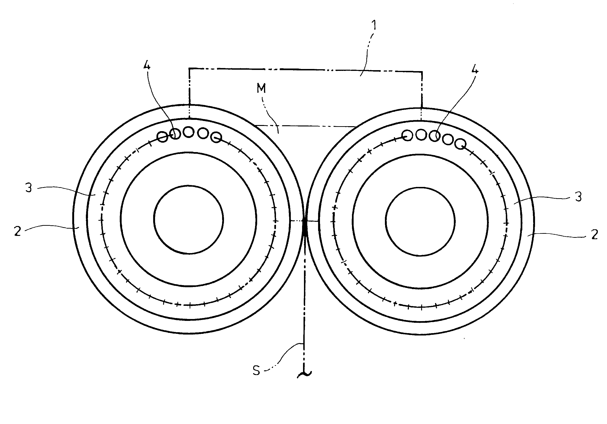
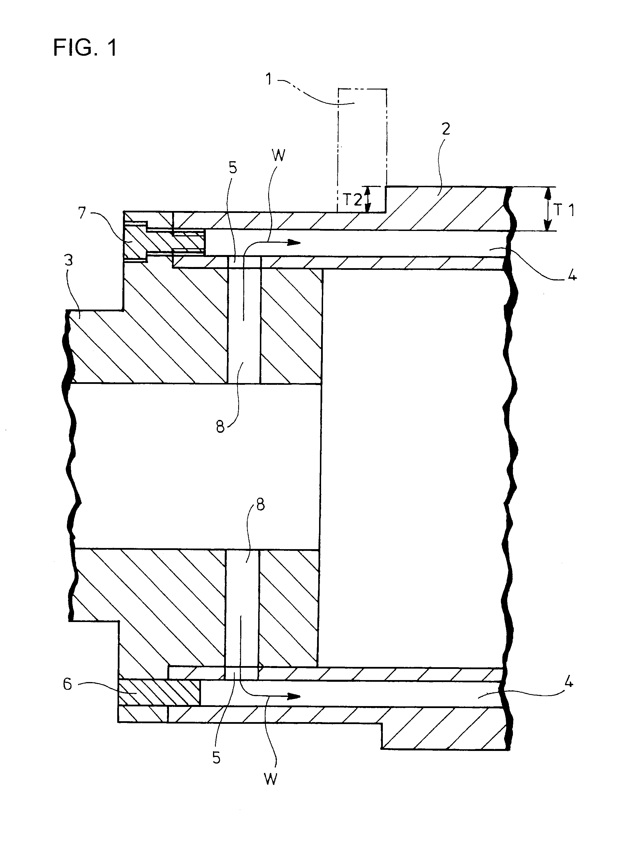
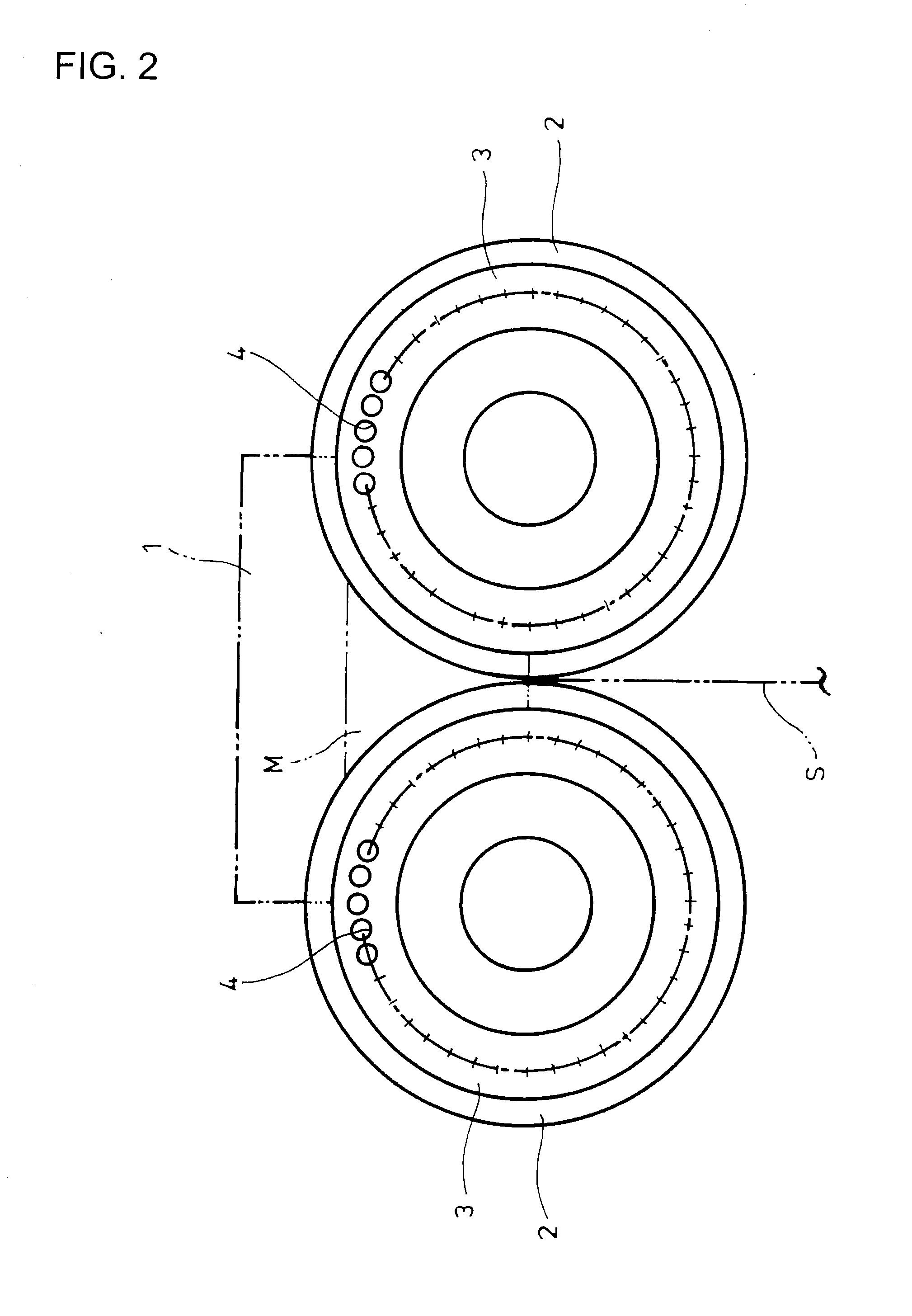
TECHNICAL FIELD[0001]The present invention relates to a casting roll.BACKGROUND ART[0002]Known as one of techniques for directly producing a strip from molten metal is twin-roll continuous casting where molten metal is supplied to between a pair of rotated rolls to deliver a solidified metal strip.[0003]FIGS. 1 and 2 show a continuous casting machine with conventional casting rolls, each casting roll comprising a cylindrical roll body 2 on which side weirs 1 abut, and hollow stub axles 3 fitted into opposite ends of the roll body 2, respectively (see, for example, Patent Literature 1).[0004]The roll body 2 is shaped such that the opposite ends have an outer diameter smaller than that of an intermediate portion. The side weirs 1 abut on end surfaces of the lager-diameter intermediate portion.[0005]The roll body 2 is formed with a plurality of longitudinal cooling passages 4 located circumferentially equidistantly and extending axially of the roll body, and a plurality of radial cooli...

Claims


Application Information

Patent Timeline
Patent Type & Authority Applications(United States)
IPC IPC(8): B22D11/06B22D11/124
CPCB22D11/0651B22D11/0682B22D11/06
Inventor NAKAYAMA, KATSUMIOTSUKA, HIROYUKIFUKASE, HISAHIKO
Owner IHI CORP
Learn More