Aspherical surface processing method, aspherical surface forming method and aspherical surface processing apparatus

a processing method and surface technology, applied in the direction of feeding apparatus, automatic control devices, programme control, etc., can solve the problems of large inertial force, large size, and complicated control of both tables, and achieve high accuracy

Active Publication Date: 2006-07-18
HOYA LENS MFG PHILIPPINES
View PDF11 Cites 1 Cited by
  • Summary
  • Abstract
  • Description
  • Claims
  • Application Information

AI Technical Summary

Benefits of technology

[0014]The present invention has been developed to solve the above problems, among others. It is thus an object of the invention to provide an aspherical surface processing method, an aspherical surface forming method, and an aspherical surface processing apparatus: capable of rapidly grinding and cutting a workpiece, having a large difference between concave and convex portions, by a simple control method using a conventional aspherical surface processing apparatus to produce a high-quality product.
[0017]As a result, the X-axis table of the aspherical surface processing apparatus moves the workpiece in a fixed direction without reciprocating it. Thus, the control method over the X-axis table is simplified and a high-performance control device for practicing the method is not required. Additionally, the X-axis table can follow the workpiece, having a large difference between the concave and convex portions, rotated at an increased revolution. Therefore, rapid and high-quality grinding and cutting can be performed by a more simplified control method compared with a conventional method.
[0024]The present invention is capable of processing an aspherical surface of an optical lens, such as a spectacle lens with high accuracy.

Problems solved by technology

Thus, the reciprocating movement control over the X-axis table and the reciprocating movement control over the Y-axis table interweave with each other, resulting in complicated control over both of the tables.
When a toric or other surface for correcting strong astigmatism, which has a large difference between the concave and convex portions, is ground and cut by a control method adopted for processing an ordinary lens, backlash develops.
Backlash may distort a grinding and cutting shape or cause other problems during the reciprocating motion.
Additionally, since the X-axis table is required to be shifted at least a distance of a radius of the workpiece, miniaturization of the X-axis table is limited, resulting in a large-size, heavy structure having a large inertial force.
It is thus difficult to finely and rapidly reciprocate the workpiece in the X-axis direction; consequently, the X-axis table cannot follow the workpiece when rotated at the same revolution as that adopted for processing an ordinary lens, when the toric or other surface is ground and cut.
There is a possibility of the X-axis table rapidly reciprocating by using a motor having extremely large output, but that is not practical.
As a result, the revolution of the workpiece is lowered to a level at which the X-axis table can follow it, which decreases productivity.

Method used


Image

  • Aspherical surface processing method, aspherical surface forming method and aspherical surface processing apparatus
  • Aspherical surface processing method, aspherical surface forming method and aspherical surface processing apparatus
  • Aspherical surface processing method, aspherical surface forming method and aspherical surface processing apparatus

Examples


embodiment 1

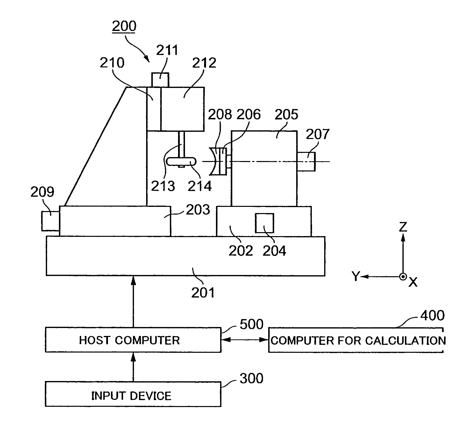
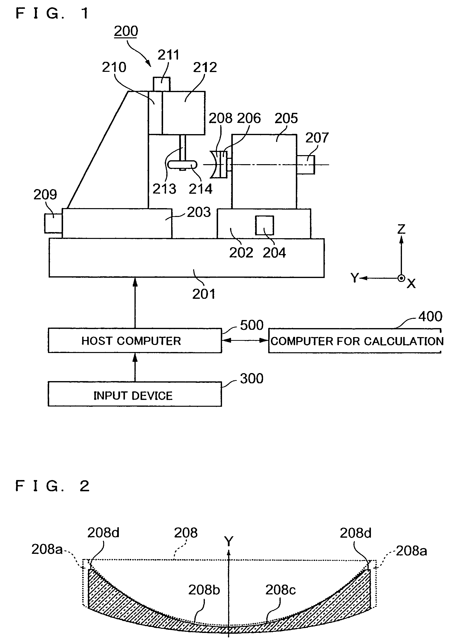
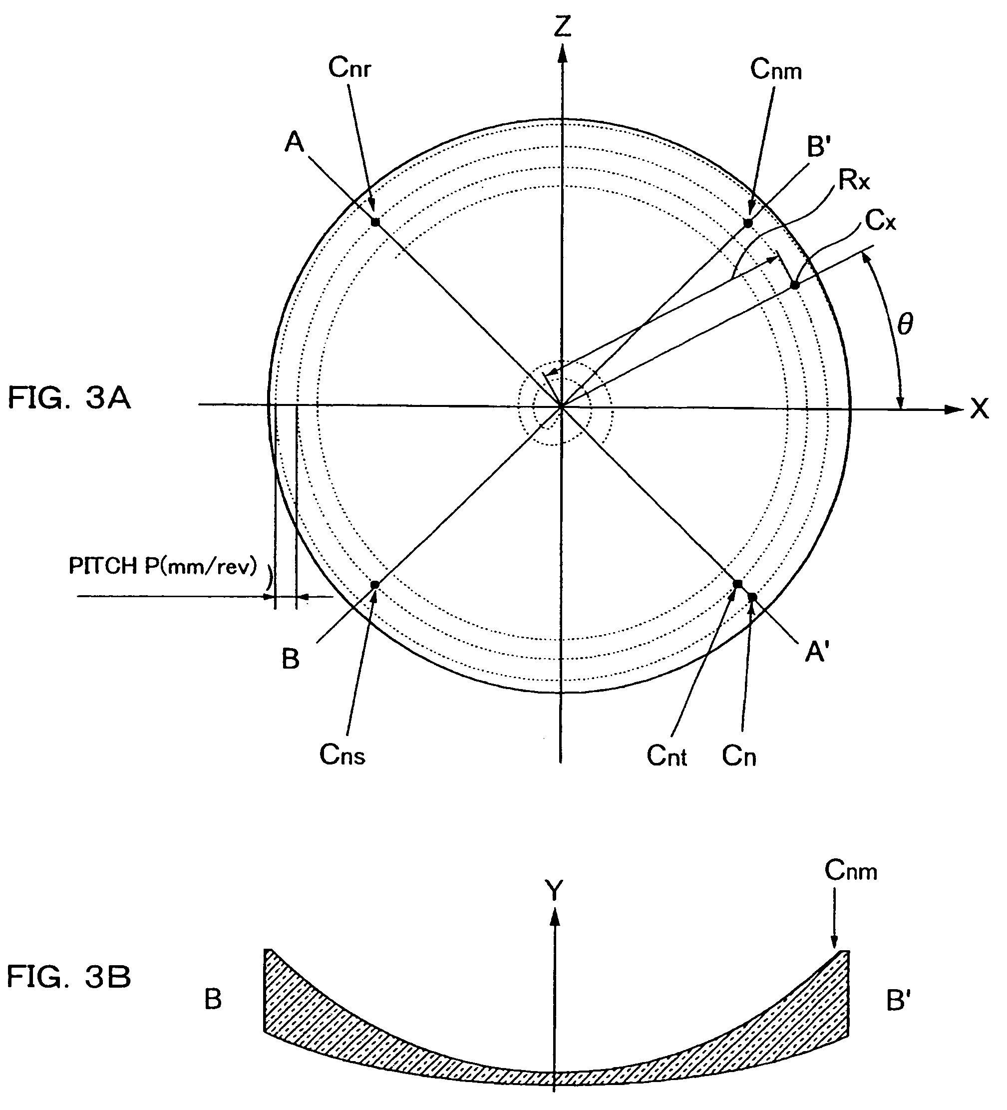
[0070]The first embodiment of the aspherical surface processing method according to an embodiment of the present invention for processing a spectacle lens (hereinafter referred to as “lens”), for example, is described in conjunction with FIGS. 3A, 3B, 4A, 4B, 5, 6 and 7. FIG. 3A is a schematic view illustrating a processed surface of the lens in the aspherical surface processing method. FIG. 3A is a front surface of the lens, while FIG. 3B is a cross-sectional view of the lens taken along a line B–B′ in FIG. 3A. FIG. 4A is a conceptual view illustrating three-dimensional coordinates of a tip surface of a rotational tool divided in a grid pattern. FIG. 4A is an elevation view, a plane view, and a side view with each showing a positional relationship between the workpiece and the rotational tool, while FIG. 4B is an enlarged view of the rotational tool shown in FIG. 4A. FIG. 5 is a conceptual view illustrating three-dimensional coordinates on a surface of the workpiece and a surface o...

embodiment 2

[0084]An aspherical surface processing method of a second embodiment according to the present invention is herein described in conjunction with FIGS. 8A, 8B, and 9. FIG. 8A is a schematic view illustrating a processed surface of a lens in an aspherical surface processing method according to a second embodiment. FIG. 8A is a front view of the lens, while FIG. 8B is a cross-sectional view of the lens taken along a line B–B′ in FIG. 8A. FIG. 9 is a conceptual view illustrating the aspherical surface processing method.

[0085]In the aspherical surface processing method of the second embodiment, the whetstone of the rotational tool 214 grinds while forming a spiral track as illustrated in FIG. 8. In this embodiment, the distance from the rotation center of the workpiece 208 to the tip center axis of the rotational tool 214 (Rx) is increased with a predetermined feed pitch. More specifically, the grinding is started at a processing point located at or adjacent to the rotation center of the ...

embodiment 3

[0099]An aspherical surface processing method of a third embodiment of the present invention is now described with reference to FIGS. 10A and 10B. FIG. 10A is a schematic view illustrating a rotational tool 214 in the aspherical surface processing method of the third embodiment. FIG. 10A is a front view of the rotational tool 214, while FIG. 10B is a side view of the rotational tool 214.

[0100]In the aspherical surface processing method of the third embodiment, a pair of cutters 216 as cutting tools each of which is provided on a circumference side of the rotational tool 214 are opposed to each other with its center interposed between the cutters 216.

[0101]Additionally, the aspherical surface processing method of the third embodiment is similar to the grinding method in which the rotational tool 214 uses a whetstone as described in the above first and second embodiments.

[0102]According to this embodiment as explained above in detail, advantages similar to those shown in the first and...


PUM

PropertyMeasurementUnit
surface roughness Rmaxaaaaaaaaaa

Abstract

An aspherical surface processing method involves a workpiece to be processed by rotating around a rotation axis, and a rotational tool movable relative to the workpiece in the same direction as the rotation axis of the workpiece and in a direction perpendicular to the rotation axis of the workpiece. The rotational tool is shifted in a fixed direction with a predetermined feed pitch in a partial or entire region from a center of the rotation axis of the workpiece to a periphery of the workpiece in the direction perpendicular to the rotation axis of the workpiece to process the workpiece into a non-axisymmetrical and aspherical surface.

Description

CROSS-REFERENCE TO RELATED APPLICATION[0001]This application claims priority from JPA 2003-369066, the complete disclosure of which is herein incorporated by reference in its entirety for all purposes.TECHNICAL FIELD[0002]The present invention relates to an aspherical surface processing method, an aspherical surface forming method, and an aspherical surface processing apparatus capable of rapidly grinding and cutting an aspherical surface having a large difference between a concave and a convex portion.BACKGROUND[0003]A so-called progressive-power lens having no dividing line has been widely used as a spectacle lens for correcting presbyopia. A recent proposal has been a so-called inside surface progressive lens, in which a progressive surface or a curved surface is formed by synthesizing a progressive surface and a toric surface provided on an eyeball-side concave surface. The inside surface progressive lens is capable of reducing oscillation and distortion, which are drawbacks of ...

Claims


Application Information

Patent Timeline
Patent Type & Authority Patents(United States)
IPC IPC(8): B24B1/00B23Q15/00B24B13/00B24B13/06B24B51/00
CPCB24B13/0012B24B51/00B24B13/06B23Q15/00B24B13/00G05B19/4093
Inventor MIYAZAWA, MAKOTO
Owner HOYA LENS MFG PHILIPPINES
Why Eureka
Try Eureka