
Internal combustion engine without connecting rod and a method of its construction

a technology of internal combustion engine and connecting rod, which is applied in the direction of positive displacement engines, reciprocating piston engines, machines/engines, etc., can solve the problems of crank mechanism kinematics, crankshaft revolution revved increase inertia forces, burden additionally the crank mechanism elements,

Active Publication Date: 2007-10-23
ENCHEVA MICHAELA ENCHEVA +1
View PDF7 Cites 1 Cited by
  • Summary
  • Abstract
  • Description
  • Claims
  • Application Information

AI Technical Summary

Benefits of technology

"The invention is a method for creating an internal combustion engine without a connecting rod that has six or more arc-like units. The method involves creating a hinged multi-unit with arc-like units that touch flexibly with the inner cylindrical surface of the engine case. The engine shaft is connected to the hinged multi-unit through gear wheels. The engine has a close geometrical figure with the arc-like units, and the pistons are fixed with piston rods that are connected flexibly to the arc-like units. The method allows for a reciprocating roll over without slipping over from one end position to another. The engine has a high degree of efficiency and compactness."

Problems solved by technology

A disadvantage of those engines is the kinematics of the crank mechanism where the reciprocating motion of the pistons is transformed into rotary motion of the crankshaft.
The crankshaft revolutions revved increase the inertia forces and burden additionally the crank mechanism elements.
A disadvantage of the crank transforming mechanism is the presence of side friction force of the pistons on the walls of the cylinders which leads to losses due to the friction and higher wear and tear of those elements.
Another disadvantage of the crank transforming mechanism is the presence of a flexible hinged link in the piston which link is formed by itself, by the piston bolt, and by the head of the connecting rod.
It increases the length of the guiding part of the pistons, of the total working length of the cylinders and thus it leads to the increase of the overall dimensions and of the engine weight.
A disadvantage of that engine is as follows: the kinematics of the mechanism for transformation of the reciprocal motion of the pistons into a rotary motion of the outgoing shaft allows the construction of engines limited with four cross-like arranged cylinders only.
Another disadvantage of that engine is the inconsistency that crops up while making clear its kinematics.
Another disadvantage of that engine is disclosed in the author's claim 2 which is not applicable because according to it “The axis of the hinged links between the teeth segments (2) and the piston rods (3) coincide with the divisor diameter of the teeth gearing”, and it is well-known from the theory of the cylindrical teeth drives that such a common “divisor diameter of teeth gearing does not exist”—there is always a tooth drive between two teeth elements, each one of them having its own divisor diameter.
Therefore, the teeth segments (2) lie between the two discs of the build-up shaft, and the same one cannot be mounted or dismounted separately as a shaft set, and those operations have to be made by means of technological manipulations with the whole engine which makes the mounting and dismounting work complex.
A general disadvantage of the internal combustion engines working with crankshaft transforming mechanism as well as of the engine without a connecting rod according to the authorship certificate No. 42948 is the fixed kinematics dependence between the revolutions of the outgoing engine shaft and the stroke frequency of their pistons.
It is impossible by programming a big number of piston strokes per time unit in advance to create an engine with lower revolutions of the outgoing engine shaft, which depending on the number of the cylinders with corresponding increase of the rotary moment not to use additional reduction gear.

Method used


Image

  • Internal combustion engine without connecting rod and a method of its construction
  • Internal combustion engine without connecting rod and a method of its construction
  • Internal combustion engine without connecting rod and a method of its construction

Examples


Embodiment Construction

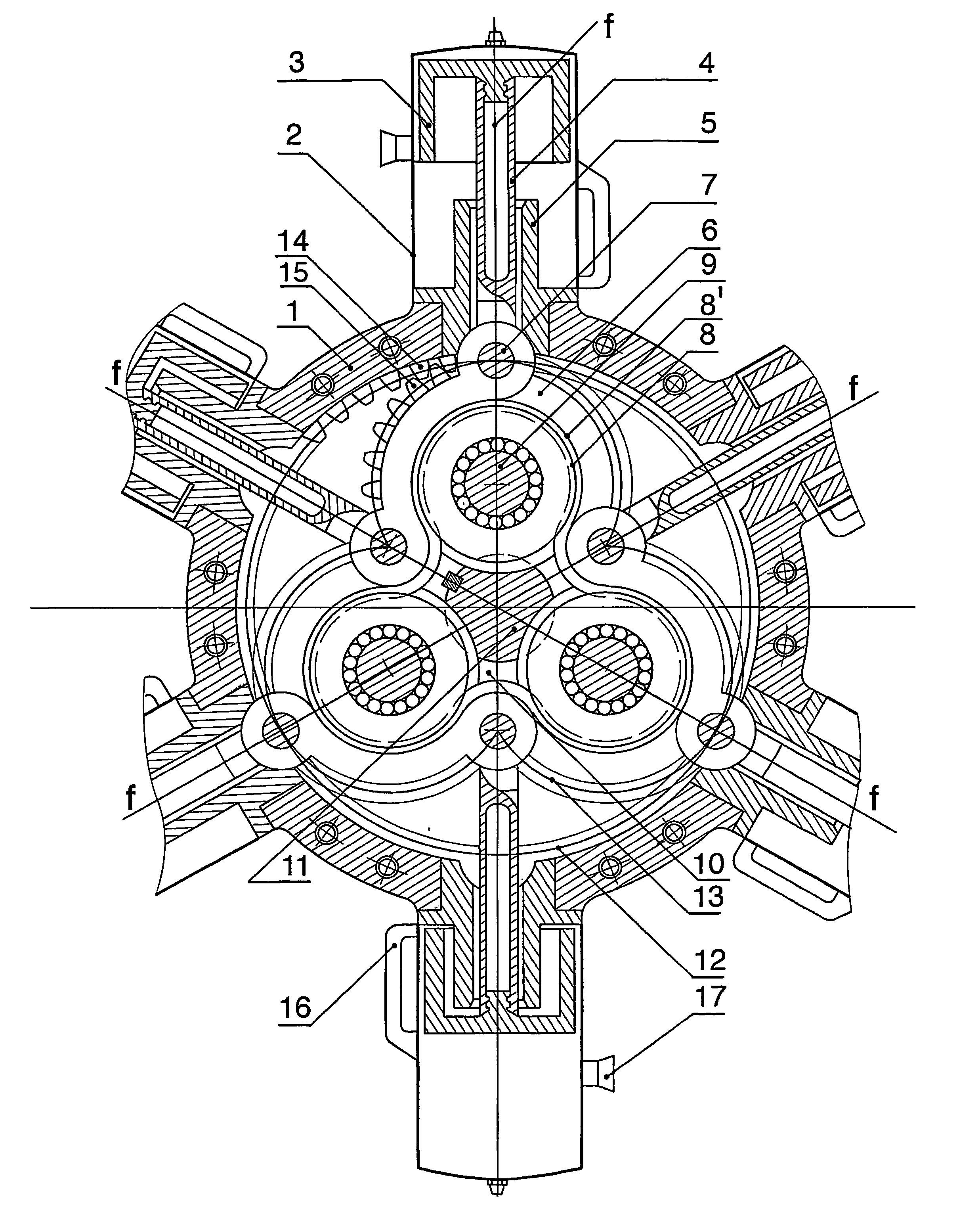
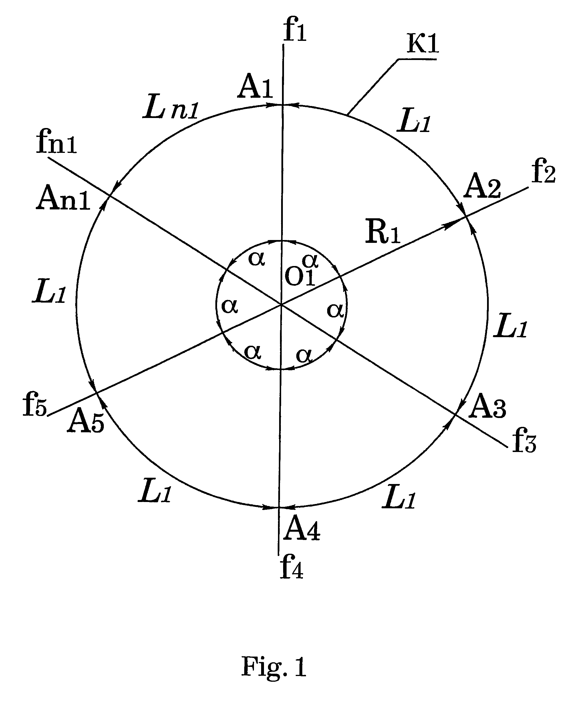
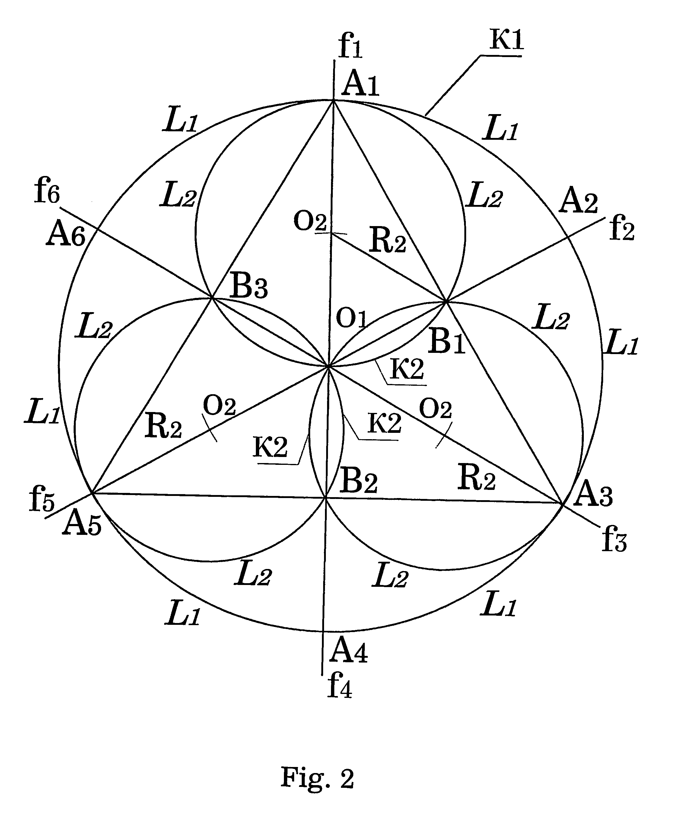
[0028]The method of construction of internal combustion engine without a connecting rod with six and more even number of arc-like units defines the consecutive steps of the engine construction, while at beginning the number of the working crank arms n1 and the stroke of the pistons S in the cylinders is programmed whereat the number of the working crank arms n1 is an even number, equal to or greater than six. The center O1 of the engine without a connecting rod is marked and depending on the even number chosen of the crank arms n1 there are drawn through the center the same number of radial beams f1 . . . fn1 (FIG. 1), which form equal central angles α among them and which are the axes lines of the working cylinders. There is drawn the basic circumference K1 with a radius R1 from the center O1 depending on the even number chosen of crank arms n1 and the stroke S of the pistons according to the relation between them

[0029]R1=S1-cos⁢⁢α

while the beams f1 . . . fn1 cross the basic circum...


PUM


Abstract

The invention relates to the structure of internal combustion engine without a connecting rod and a method of its construction. The proposed method of construction describes the consecutive steps in creating the engine and allows the creation of internal combustion engine without a connecting rod with six and more even number of arc-like units (6) whereat the heating of the opposite arc-like units (6) in the center O.sub.1 of the engine is removed. The complex mounting and dismounting of the engine shaft is eliminated too, because according to the invention the engine shaft is not articulated of several details, but it is whole, uncut. Besides, the possibility is obtained for a change of the revolutions of the engine shaft (11) without reductor in one and the same stroke frequency of the pistons (3) movement by changing only the number of working cylinders of the engine.

Description

TECHNICAL FIELD[0001]The invention relates to the structure of internal combustion engine without a connecting rod and a method of its construction designed for operation of transport vehicles as well as power aggregates set in motion and situated in industry and agriculture.BACKGROUND OF THE INVENTION[0002]Star-like aircraft internal combustion engines including circular case with mounted on it nine radial arranged cylinders and pistons lying in the same plane are already well-known. (For example:“Star-like aircraft engine cross section named Lajkoming” Eng. Julius Mezkerle, “Vehicle engines with air cooling” page 220, Moscow 1959; translation from Czech into Russian; Nine cylinder aircraft engine “AIII-62 P” Petr S. Labasin, “Aircraft engine AIII-62 P”, page 22, Moscow, 1972, including circular case with mounted on it and lying in one plane up to nine radial situated cylinders with pistons. The pistons are connected flexibly by piston bolts and by connecting rods with joined crank...

Claims


Application Information

Patent Timeline
Patent Type & Authority Patents(United States)
IPC IPC(8): F02B75/22F16H25/08F01B1/06F01B9/06
CPCF01B1/062F01B9/06Y10T74/18296F02B75/222F01B1/06F02B75/00
Inventor ENCHEV, ENCHO MIHAYLOV
Owner ENCHEVA MICHAELA ENCHEVA
Learn More