

Electronic device and circuit for providing tactile feedback
a technology of tactile feedback and electronic devices, applied in the direction of generators/motors, pulse techniques, instruments, etc., can solve the problems of difficult optimization of piezoelectric actuator drive circuits, the domino switch does not function well with morphing graphic user interfaces, and the inability to selectively feedback individual input locations (keys, buttons, arrows, etc., to achieve low cost
- Summary
- Abstract
- Description
- Claims
- Application Information
AI Technical Summary
Benefits of technology
Problems solved by technology
Method used
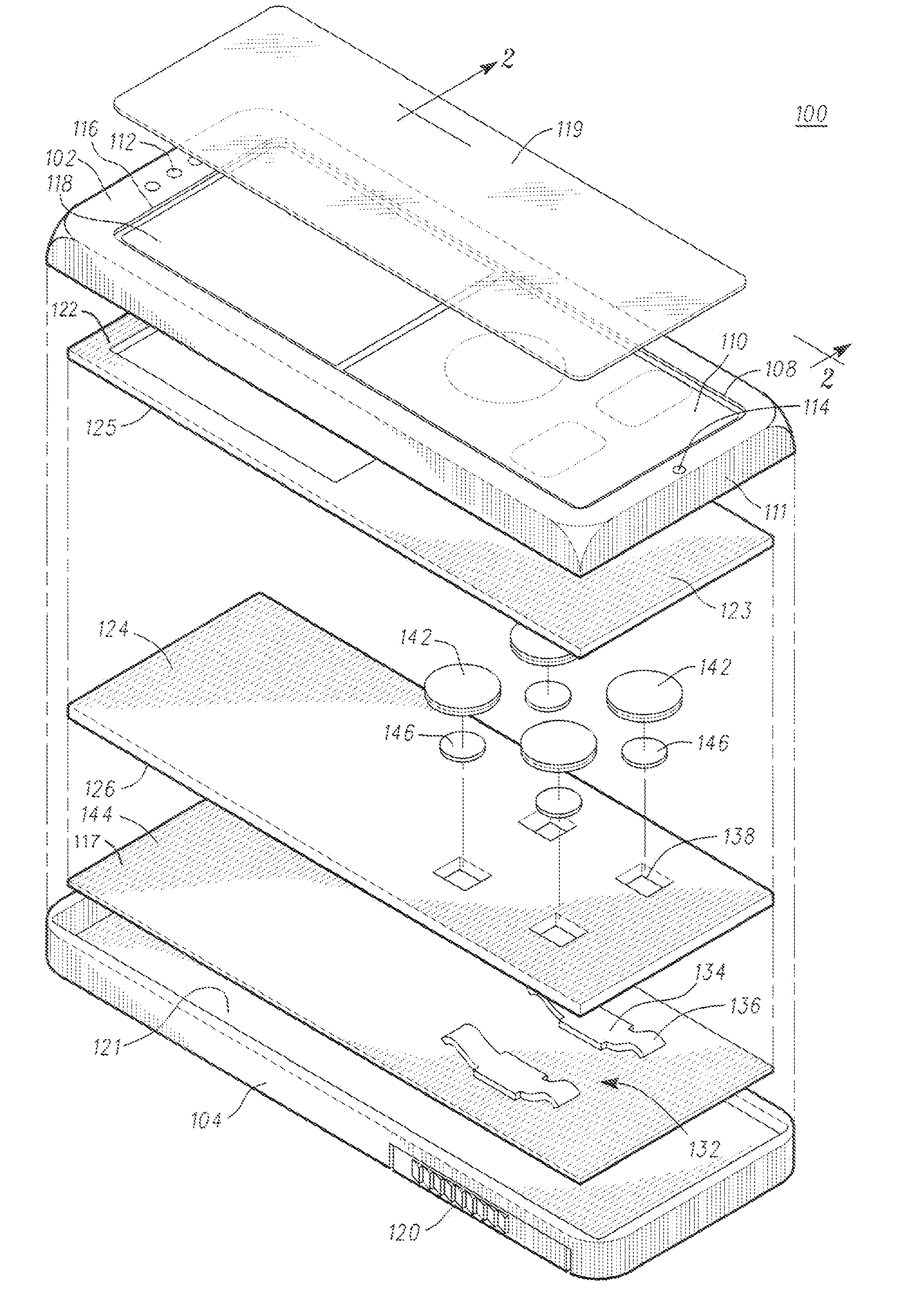
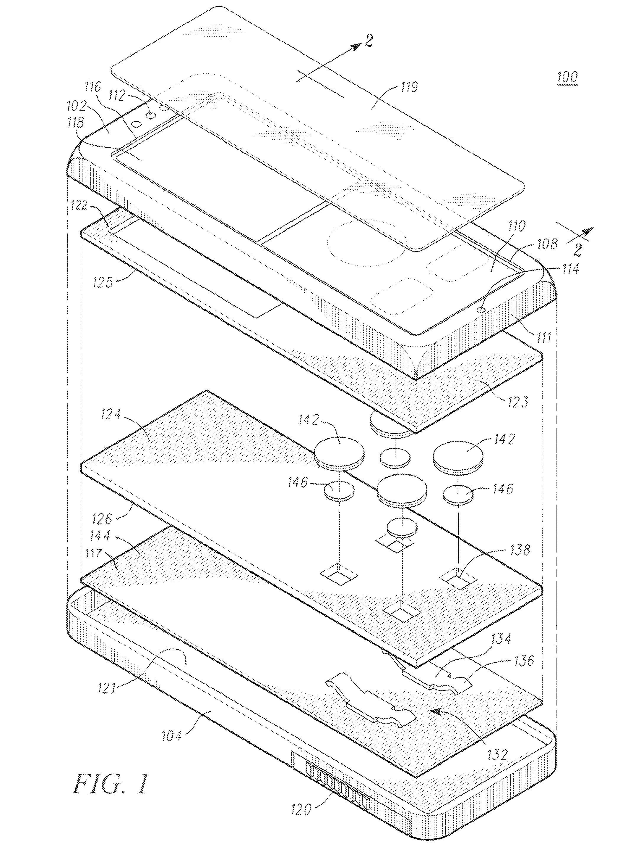
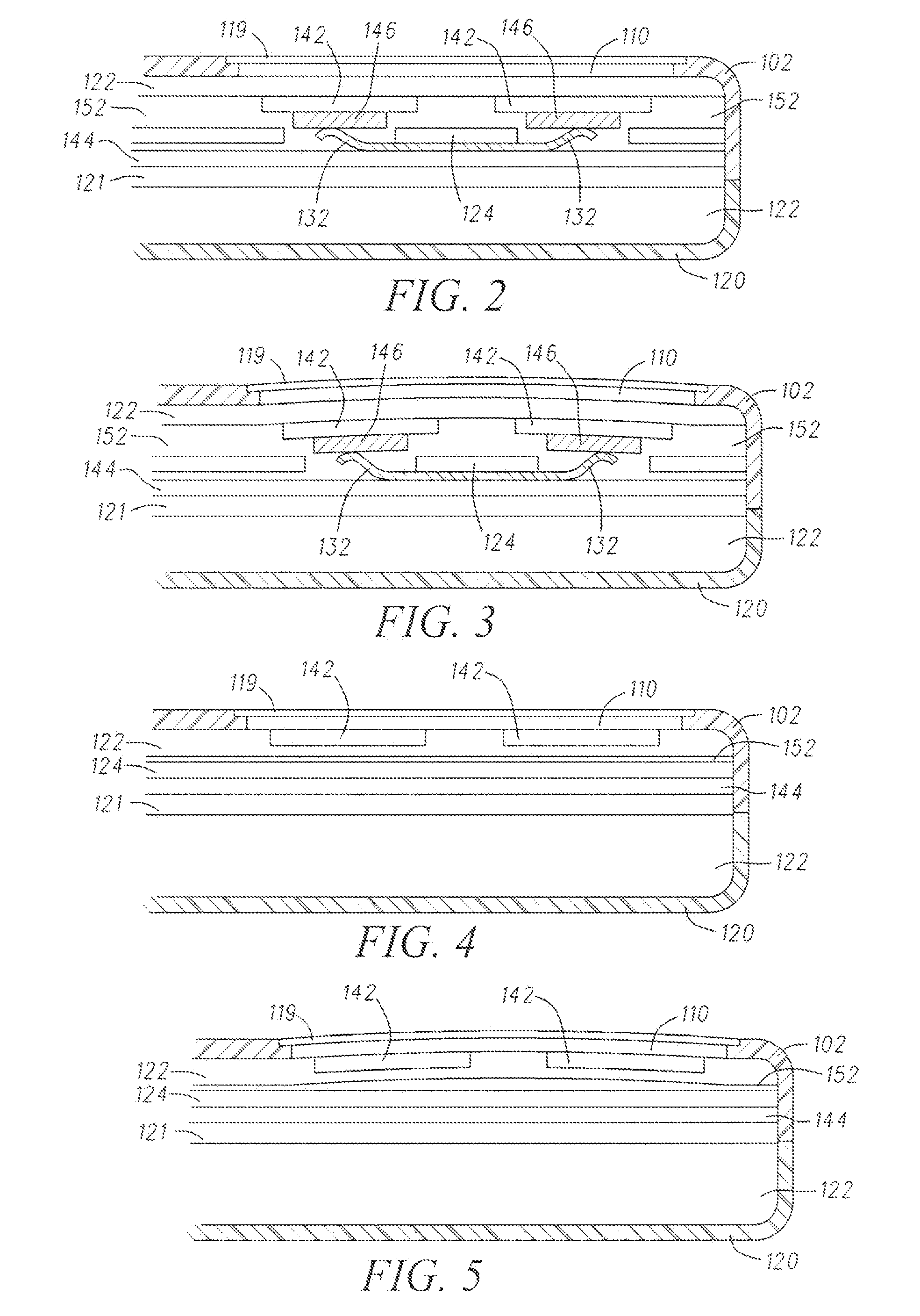
Image

Examples
Embodiment Construction
[0024]The following detailed description of the invention is merely exemplary in nature and is not intended to limit the invention or the application and uses of the invention. Furthermore, there is no intention to be bound by any theory presented in the preceding background of the invention or the following detailed description of the invention.
[0025]The electronic circuitry for controlling at least one piezoelectric actuator includes a piezoelectric actuator drive circuit that includes a pulsed, inductive boost charging circuit, operatively responsive to a first pulse-width-modulated control signal, and a pulsed constant-current-sink discharge circuit that is operatively responsive to a second pulse-width-modulated control signal. The pulse-width-modulated control signals may be such that the duty cycle remains constant, or the duty cycle may vary as a function of time. The pulsed inductive boost circuit controllably adds pre-determined “packets” of charge to the piezoelectric act...
PUM
 Abstract
Description
Claims
Application Information