Stepping Motor

a stepping motor and stepping plate technology, applied in the direction of dynamo-electric machines, instruments, clocks, etc., can solve the problems of possible unstably supported inner yoke 121, cutting planes liable to deformation, etc., to achieve the effect of less leakage flux, less magnetic resistance, and less leakage flux

Inactive Publication Date: 2009-03-19
MINEBEA MOTOR MFG
View PDF3 Cites 2 Cited by
  • Summary
  • Abstract
  • Description
  • Claims
  • Application Information

AI Technical Summary

Benefits of technology

[0014]In the present invention, since the tubular bending part is formed in at least the outer yoke and the outer yoke comes into contact with the outer peripheral surface of the cylindrical core in the inner peripheral surface of the bending part, the contact area of the outer yoke and the core can be increased and a magnetic resistance at the contact part of the outer yoke and the core can be reduced, and thus, a leakage flux can be decreased. As a result, a compact stepping motor having a small diameter can be provided in which a motor torque is not deteriorated.
[0015]Further, in the present invention, since the tubular bending part is formed in each of the inner and outer yokes and the inner peripheral surface of the bending part comes into contact with the outer peripheral surface of the cylindrical core, each of the contact area of the inner yoke and the core and the contact area of the outer yoke and the core can be increased, and thus, a magnetic resistance at the contact part of the inner yoke and the core and at the contact part of the outer yoke and the core can be reduced, so that a leakage flux can be more decreased. As a result, a compact stepping motor having a small diameter can be provided in which a motor torque is not more deteriorated.
[0016]Further, since the rotor has the recessed part provided at the part opposed to the bending part of the inner yoke in the stators at both sides in the direction of the shaft, the rotor can be arranged in a narrow space without reducing a magnetic force.

Problems solved by technology

Therefore, cutting planes are liable to be deformed.
However, since the thickness is relatively small, the inner yoke 121 may be possibly unstably supported.

Method used


Image

  • Stepping Motor
  • Stepping Motor
  • Stepping Motor

Examples


first embodiment

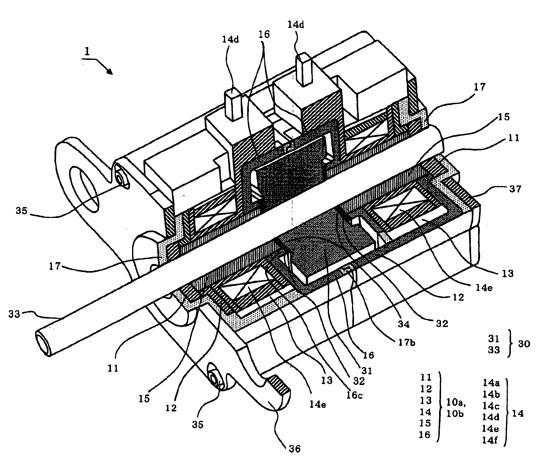
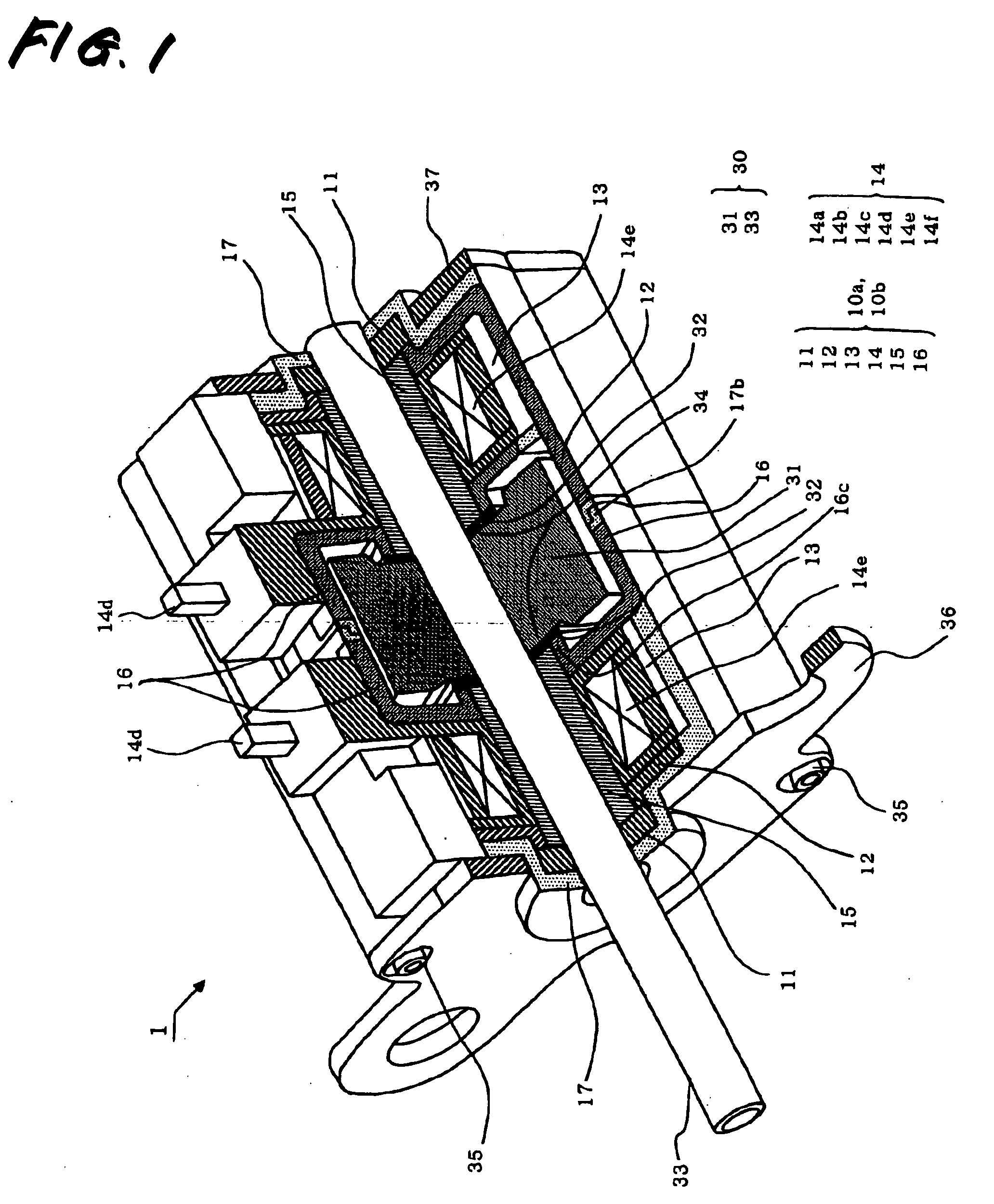
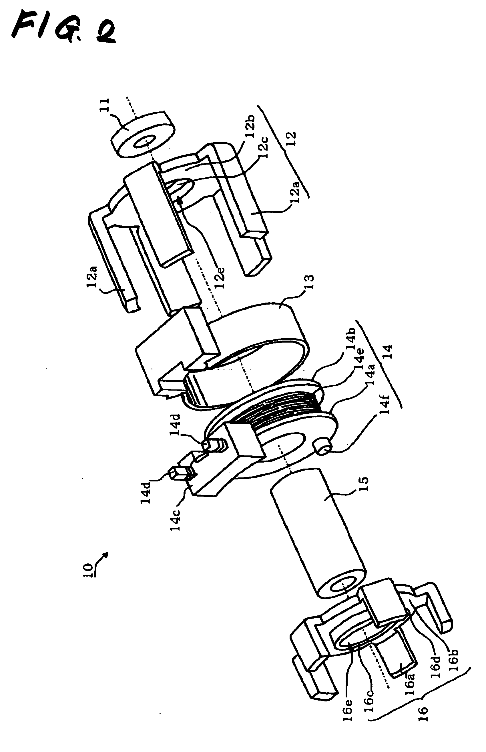
[0059]FIG. 1 is a partly sectional perspective view showing a structure of a stepping motor of the present invention. FIG. 2 is an exploded perspective view in a stator shown in FIG. 1. FIG. 3 is a perspective view showing a completed state of the stator by a resin mold. FIG. 4 is a schematic view showing a fitting state of an inner yoke, an outer yoke and a core. In a stepping motor 1, stators 10a and 10b having the same forms are arranged to be opposed at both end sides in the direction of a shaft (an axial direction) of a rotor magnet 31.

[0060]The stator 10 (10a, 10b) includes a bearing 11, an outer yoke 12, a covering 13, a bobbin 14, a core 15 and an inner yoke 16. The bearing 11 supports a shaft 33 of a rotor 30, and is formed with, for instance, an oil impregnated sintered bearing. It is to be understood that a ball bearing may be used.

[0061]The outer yoke 12 and the inner yoke 16 are formed with, for instance, a soft magnetic material such as an electro-galvanized steel plat...


PUM


Abstract

A stepping motor has stators arranged at both end sides in the direction of a shaft of a rotor magnet, each of the stators includes inner and outer yokes having pole teeth opposed to the outer peripheral surface of the rotor magnet, at least the outer yoke among the inner and outer yokes has a tubular bending part, and the bending part is fixed to a cylindrical core made of a magnetic material.

Description

TECHNICAL FIELD[0001]The present invention relates to a stepping motor used for an actuator of an optical disk device or a video camera, and more particularly to a stepping motor having stators that are arranged at both end sides in the direction of a shaft of a rotor and include inner and outer yokes each having pole teeth, in which the inner and outer yokes are stably provided in a cylindrical core with wide contact areas.BACKGROUND ART[0002]Usually, with a request for the miniaturization of various kinds of electronic devices, a motor accommodated in the device is also requested to be miniaturized to meet a space for accommodating the motor. For this request, a stepping motor having a compact form and a small diameter, which includes stators arranged at both ends in the axial direction of a rotor magnet, has been proposed (for instance, see Patent Document 1). In FIGS. 6 and 7, the structure of the stepping motor is shown. FIG. 6 is an exploded perspective view and FIG. 7 is a se...

Claims


Application Information

Patent Timeline
Patent Type & Authority Applications(United States)
IPC IPC(8): H02K37/12
CPCH02K37/14H02K1/145
Inventor YAMAWAKI, TAKAYUKIOHYASHIKI, TAKETOSHI
Owner MINEBEA MOTOR MFG
Why Eureka
Try Eureka