Organic electro-luminescent display device

Inactive Publication Date: 2009-03-19
CHOI BEOHM ROCK +5
View PDF4 Cites 20 Cited by
  • Summary
  • Abstract
  • Description
  • Claims
  • Application Information

AI Technical Summary

Problems solved by technology

As a result, although there is high light efficiency, the red, green and blue light cannot be minutely separated from each other.
In addition, when using the color transf

Method used


Image

  • Organic electro-luminescent display device
  • Organic electro-luminescent display device
  • Organic electro-luminescent display device

Examples


Embodiment Construction

[0028]Preferred embodiments of the present invention will be described below in more detail with reference to the accompanying drawings. This invention may, however, be embodied in different forms and should not be construed as limited to the embodiments set forth herein. Rather, these embodiments are provided so that this disclosure will be thorough and complete, and will fully convey the scope of the invention to those skilled in the art.

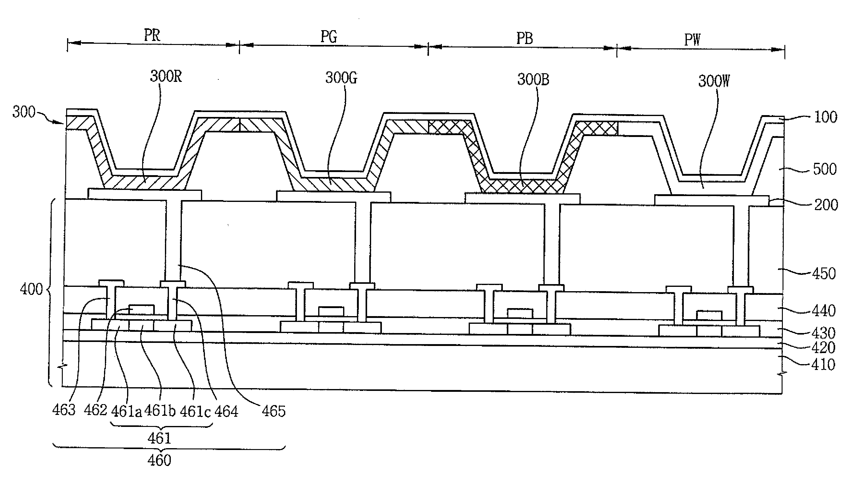
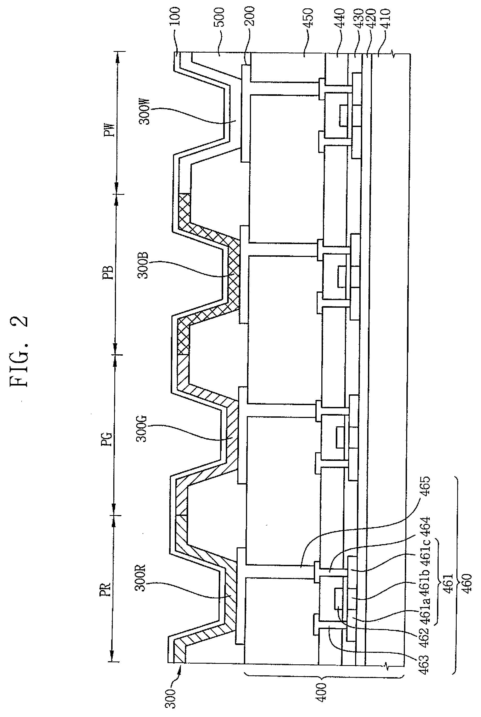
[0029]FIG. 2 is a structural view showing an OELD device according to an embodiment of the present invention. The OELD device shown in FIG. 2 forms a full color image using an independent RGB layer structure. The OELD device is a bottom generation type OELD device, wherein a light for displaying an image is generated at a bottom portion of the OELD device and is provided downwards.

[0030]Referring to FIG. 2, the OELD device includes a first electrode 100, and a plurality of second electrodes 200 thereby forming a plurality of sub-pixels with the fi...


PUM


Abstract

A display device comprises a first electrode formed on a substrate, a plurality of second electrodes formed on the substrate below the first electrode, an organic luminescent layer formed between the first electrode and the plurality of second electrodes, and a color filter layer formed on the substrate, wherein the color filter layer includes a red filter, a green filter, a blue filter and a white filter.

Description

CROSS-REFERENCE TO RELATED APPLICATIONS[0001]This application is a divisional of U.S. patent application Ser. No. 10 / 788,153, filed Feb. 26, 2004, which claims priority to Korean Patent Application No. 2003-21644 filed on Apr. 7, 2003, the contents of which are incorporated herein by reference in their entireties.BACKGROUND OF THE INVENTION[0002]1. Technical Field[0003]The present disclosure relates to an organic electro-luminescent display device, and more particularly to an organic electro-luminescent display device using a 4-color system for forming a color image.[0004]2. Discussion of the Related Art[0005]An organic electro-luminescent display (OELD) device such as an active matrix organic light emitting diode (AMOLED) may include an anode including a transparent electrode made from, for example, indium tin oxide (ITO), a cathode including a metal electrode having a low work function, and an organic luminescent layer including an organic thin layer interposed between the anode a...

Claims


Application Information

Patent Timeline
IPC IPC(8): H01J1/63H01L27/32H05B33/12H01L51/50H05B33/14H05B33/22H05B33/26
CPCH01L27/3213H01L27/3244H01L27/322H10K59/351H10K59/38H10K59/12H05B33/14
Inventor CHOI, BEOHM-ROCKCHOI, JOON-HOOCHUNG, JAE-HOONCHUNG, JIN-KOOLEE, DONG-WONLEE, SANG-PIL
Owner CHOI BEOHM ROCK
Why Eureka
Try Eureka