Ink jet printing apparatus and ink jet printing method

Inactive Publication Date: 2009-03-19
CANON KK
View PDF6 Cites 23 Cited by
  • Summary
  • Abstract
  • Description
  • Claims
  • Application Information

AI Technical Summary

Benefits of technology

[0022]The present invention provides an ink jet printing apparatus and method that scans a print head, which ejects large and small ink droplets of different volumes, in forward and backward directions an odd nu

Problems solved by technology

Such lines of image defects often occur in areas with high ink dot densities (high print duties).
As a result of this end nozzle droplet deflection, ink droplets ejected from those nozzles situated near the ends of the nozzle array land at positions, i.e., dot forming positions, deviated from intended ones, leading to a possibility of lines of image defects being formed as shown in FIG. 13.
Making the ink droplets large, however, contributes to showing more distinctively the granularity of the dots formed on a print medium,

Method used


Image

  • Ink jet printing apparatus and ink jet printing method
  • Ink jet printing apparatus and ink jet printing method
  • Ink jet printing apparatus and ink jet printing method

Examples


first embodiment

(First Embodiment)

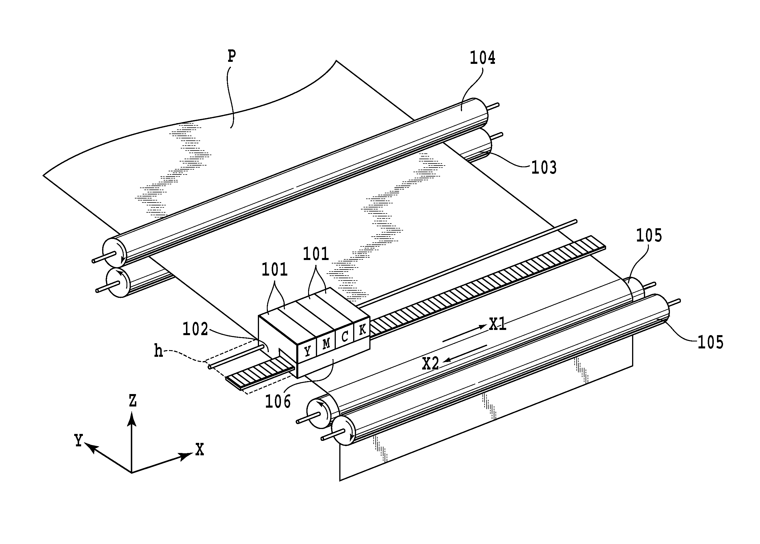
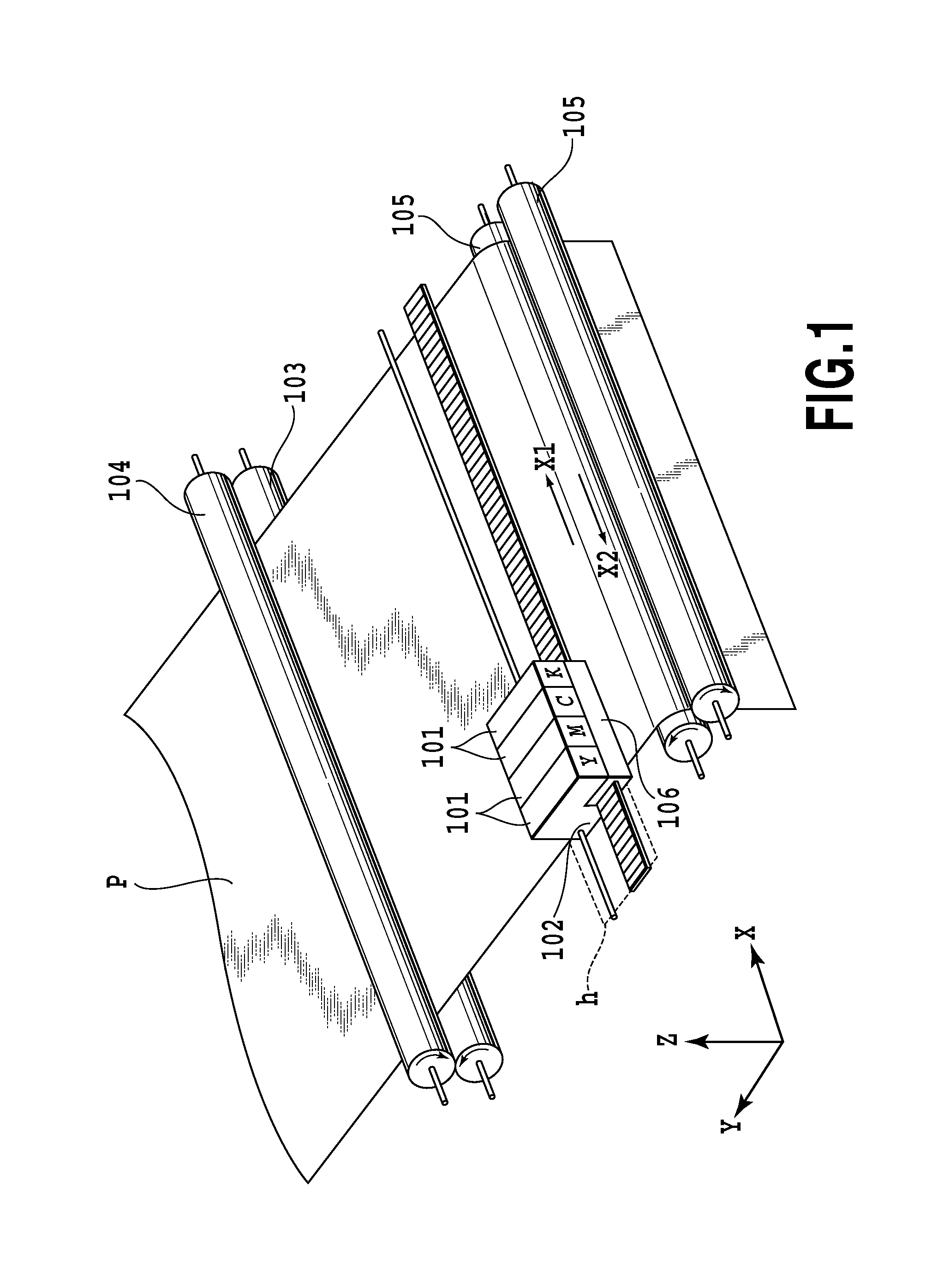
[0046]FIG. 1 is a perspective view showing an essential part of an ink jet printing apparatus applicable to this invention. Reference number 101 represents four ink cartridges, each composed of an ink tank and a print head (multi-head) 102 having a plurality of arrays of printing elements integrally formed therein. These ink tanks accommodate black (K), cyan (C), magenta (M) and yellow (Y) inks. The print head 102 may be formed separated from the ink tank. Each of the printing elements in the print head 102 includes an ink ejection opening and a corresponding ejection energy generation element. As the ejection energy generation element a heater (heating resistive element) and a piezoelectric element may be used. In the following description, a portion including such an ink ejection opening and an ejection energy generation element is called a “nozzle”.

[0047]Denoted 103 is a paper feed roller which, together with an auxiliary roller 104, keeps a sheet of paper (prin...

second embodiment

[0105]In the first embodiment, cyan ink ejection openings include large ink ejection openings and small ink ejection openings. Like the cyan ink ejection openings, a magenta ink ejection openings of this embodiment also include large ink ejection openings and small ink ejection openings. A print head of this embodiment has equal ink droplet landing areas in both the forward scans and the backward scans. So, there is no print ratio difference between all forward scans and all backward scans, as is observed in FIG. 15B and FIG. 15C.

[0106]In this embodiment, a relation between a quantization level (grayscale level) of image data and dot patterns of cyan and magenta inks is the same as that shown in FIG. 4 of the preceding embodiment.

(First Print Mode)

[0107]A first print mode of this embodiment uses thinning patterns of FIGS. 5A, 5B, 5C and FIGS. 6A, 6B, 6C, as in the first embodiment, for cyan ink and magenta ink print data. That is, print data to form small dots S of cyan and magenta ...


PUM


Abstract

When completing an image in a predetermined area by an odd or even number of bidirectional printing scans, this invention makes it possible to suppress lines of image defects and density variations and thereby print a high-quality image at high speed. In completing an image by an odd number of bidirectional printing scans, the print data for small ink droplets and large ink droplets are thinned using the first and second thinning pattern. The first and second thinning pattern thin the print data for small ink droplets and large ink droplets so that a difference between the total print ratio of all forward printing scans of the odd number of scans and the total print ratio of all backward printing scans of the odd number of scans when the first thinning pattern is used differs from that when the second thinning pattern is used.

Description

BACKGROUND OF THE INVENTION[0001]1. Field of the Invention[0002]The present invention relates to an ink jet printing apparatus and an ink jet printing method that complete an image in a predetermined print area on a print medium by performing a bidirectional printing scan of a print head capable of ejecting ink.[0003]2. Description of the Related Art[0004]Ink jet printing apparatus have been used widely as printing apparatus with functions of printer, copying machine and facsimile and as output devices for composite electronic devices such as computers and word processors and for workstations. These printing apparatus form an image (including letters) on a print medium such as paper and plastic sheets according to image information (letter information included). Since ink jet printing apparatus eject ink from a print head onto a print medium, a resolution of the printed image can be enhanced and a printing speed increased with greater ease than other types of printing apparatus. The...

Claims


Application Information

Patent Timeline
IPC IPC(8): B41J29/38
CPCB41J19/142B41J2/2125
Inventor KANDA, HIDEHIKOYAMAMOTO, WAKAKOHAMASAKI, YUJIYOSHIKAWA, HIROKAZUSAKAMOTO, ATSUSHI
Owner CANON KK
Why Eureka
Try Eureka