Heat sink structure for a power supply

a technology of heat sink and power supply, which is applied in the direction of electrical equipment, electrical apparatus, electrical apparatus contruction details, etc., can solve the problems of unfavorable heat dissipation of the whole power supply, difficult to reduce the physical volume, and complicated design, so as to improve the undesirable heat dissipation of the conventional housing, increase physical volume, and naturally dissipate heat

Inactive Publication Date: 2009-03-19
TOUCH ELECTRONICS +1
View PDF3 Cites 81 Cited by
  • Summary
  • Abstract
  • Description
  • Claims
  • Application Information

AI Technical Summary

Benefits of technology

[0011]It is the other objective of this invention to provide a conventional heat sink structure of the power supply, which improves the undesirable heat dissipation of the conventional housing of power supply, the complicated structure caused by an additional fan, or the increasing physical volume caused by an additional air chamber provided inside.
[0012]The structure comprises a high thermally conductive case (that may be made of a metal or a high thermally conductive material), being defined that a receiver space is provided to receive a power module, in which a thermally conductive part is provided on the case to contact a heating component of the power module in the power supply to induct the heat caused by the heating component to the case and then directly contact the exterior air through the outside surface of case to dissipate the heat naturally; and a housing the inner surface of which directly contact and cover the outside of high thermally conductive case, in which a grid-formed structure that communicates inside and outside is formed at most of the region of housing to prevent the heat conducted to the heat sink surface of highly thermally conductive case from scalding the person who directly touches the case. With the large heat dissipation area of high thermally conductive case matching with the grid-formed structure, the heat may directly fast be transferred for convection through the external air to increase the efficiency of heat dissipation, and further all power parts may operate in the condition of lower temperature to increase the work efficiency of power supply.

Problems solved by technology

When the heat is vented, the whole power supply is made to stay in an undesirable status of high temperature.
However, those who are skilled in the art know that such a design is apparently complicated, gives a physical volume that is not easily reduced, make higher the manufacturing cost, and brings a defect of induction of the dust in the air into the housing and then pollution to the power module 30 due to the fans enhancing the ventilation, which is not what we expect.
Thus, the formed air chamber relatively makes the physical volume of product large, which is disadvantageous to the product that is increasingly designed for miniaturization.
Further, obviously, the effect of direct heat dissipation brought by the structure is not still desirable.

Method used


Image

  • Heat sink structure for a power supply
  • Heat sink structure for a power supply
  • Heat sink structure for a power supply

Examples


Embodiment Construction

[0019]Now, the present invention will be described more specifically with reference to the following embodiments. It is to be noted that the following descriptions of preferred embodiments of this invention are presented herein for purpose of illustration and description only; it is not intended to be exhaustive or to be limited to the precise form disclosed.

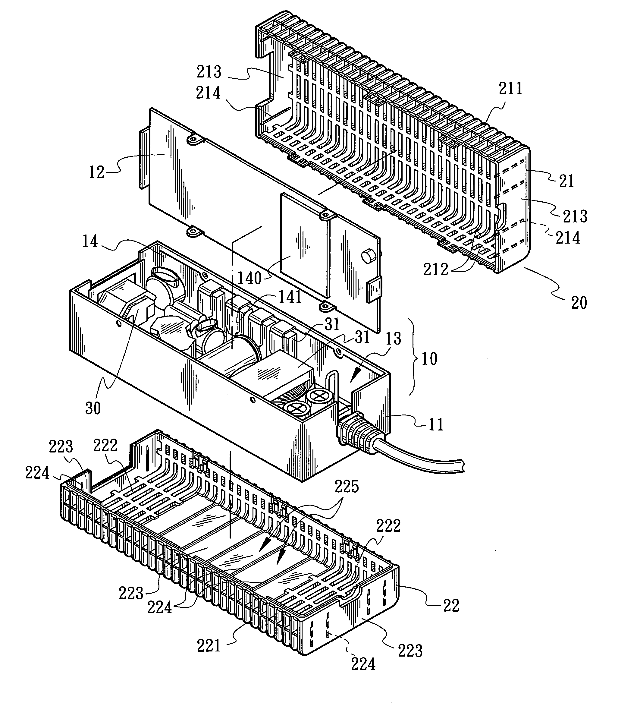
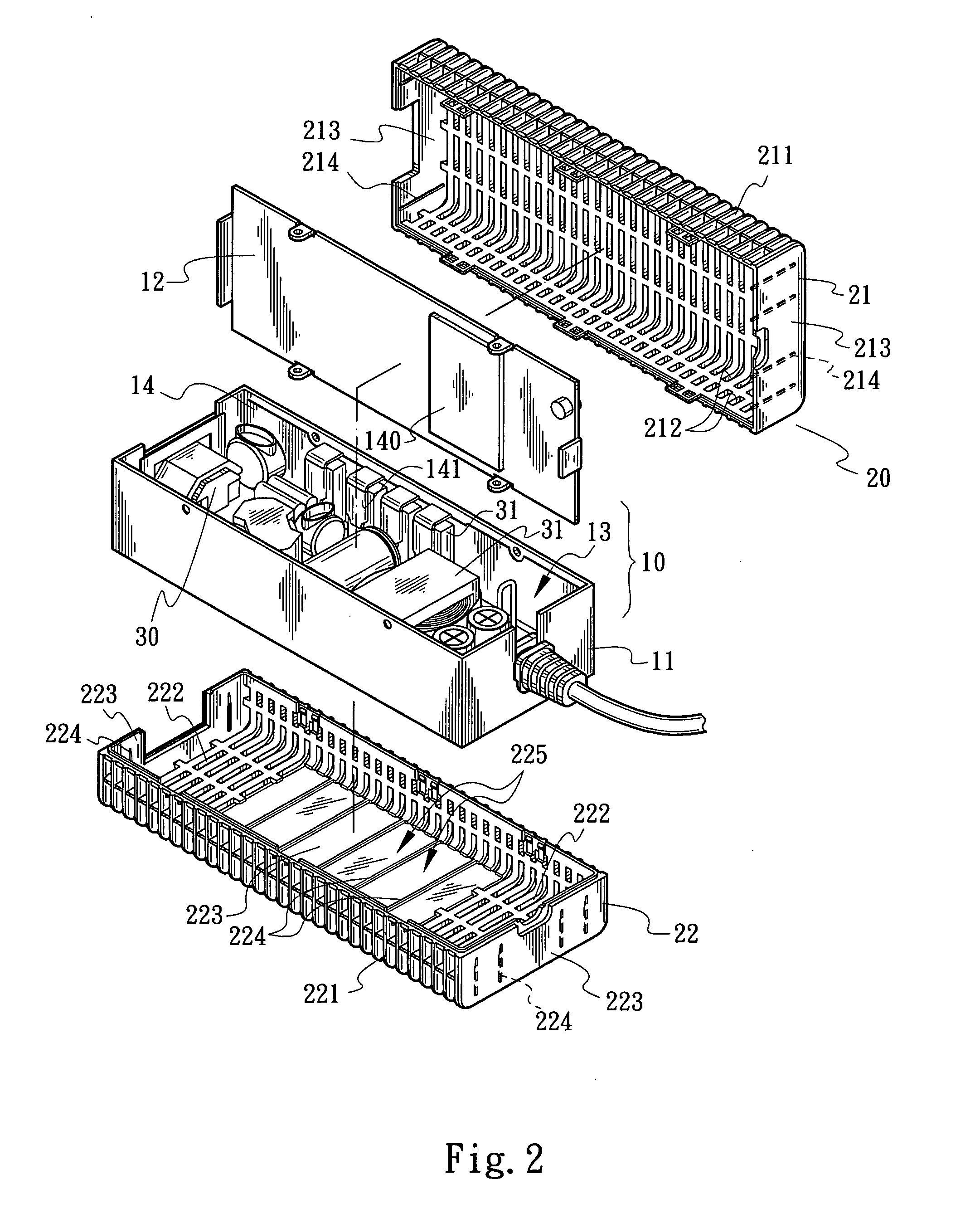
[0020]With reference to FIG. 2 illustrating a heat sink structure for a power supply in a preferred embodiment of this invention, the power supply comprises a high thermally conductive case 10 (that may be made of a metal or a non-metallic material), in which the case 10 is provided with a case 11 and a cover 12 that may be combined with the case 11, in which a receiver space 13 is formed to receive a power module 30. On the high thermally conductive case 10, thermally conductive parts 14 and 140 are provided and contact the heating component 31 of the power module 30. In the embodiment, the thermally conductive parts 14 and 140...


PUM


Abstract

A structure comprises a high thermally conductive case with a receiver space for a power module, a thermally conductive part being provided on the case to contact a heating component of the power module in the power supply to induct the heat by the heating component to the case and contact the exterior air through the outside surface of case to dissipate the heat; and a housing the inner surface of which directly contact and cover the outside of high thermally conductive case, a grid-formed structure being formed at most of the region of housing to prevent the heat from scalding the person who touches or takes the power supply. With the large heat dissipation area, the heat is transferred through the external air to increase the efficiency of heat dissipation, and further all power parts may operate in a lower temperature to increase the work efficiency of power supply.

Description

BACKGROUND OF THE INVENTION[0001]1. Field of the Invention[0002]This invention relates to a heat sink structure for a power supply and particularly to a heat sink structure that may promptly conduct out heat caused by an internal heating component and then quickly dissipate the heat by using air convection and prevent a human body from being scalded.[0003]2. Description of Related Art[0004]Along with electronic products that are continuously improved in the technology of manufacturing, all various devices are developed for a miniaturization scale without exception, such as a laptop PC, a LCD and the like as electronic products. For saving more space, a product designer even strives to refine a device body and peripherals thereof.[0005]For example, for the demand of power, an electronic product is generally provided with a power supply for long-term and stable operation. With reference to FIG. 1, a conventional power supply provided for and supplying power to the electronic device fo...

Claims


Application Information

Patent Timeline
Patent Type & Authority Applications(United States)
IPC IPC(8): H05K7/20
CPCH05K7/209
Inventor PENG, YUN-WEN
Owner TOUCH ELECTRONICS
Why Eureka
Try Eureka