Particulate mitigating propellant management tank device

a technology of propellant management and propellant, which is applied in the direction of machines/engines, combustion types, lighting and heating apparatus, etc., can solve the problems of wicking remaining residual fuel, half-oval portions wiggle around within the tank, half-oval portions bending and sag within the tank, etc., to reduce particulate contamination, reduce particulate contamination, and reduce particulate contamination

Active Publication Date: 2009-03-19
THE AEROSPACE CORPORATION
View PDF10 Cites 0 Cited by
  • Summary
  • Abstract
  • Description
  • Claims
  • Application Information

AI Technical Summary

Benefits of technology

[0008]Another object of the invention is to provide a fuel wick in a propellant tank for wicking fuel within the tank with reduced particulate contamination.
[0009]Yet another object of the invention is to provide a fuel wick having curved flanges in a propellant tank for wicking fuel within the tank with reduced particulate contamination.
[0010]Still another object of the invention is to provide a fuel wick having four half-oval portions with respective curved flanges touching the interior sides in a propellant tank for wicking fuel within the tank with reduced particulate contamination.
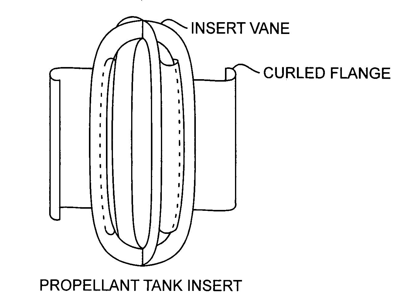
[0011]The invention is directed to a propellant tank wick having curved edges abutting the interior side of the tank for reducing particulate generation and fuel contamination. Discovery is made that moving wicks can cause particulate contamination with a fuel tank. The discovered heretofore unknown problem of particulate generation by wick scratching results from an exterior edge of the wick making moving contact with the interior sides of a moving tank. The edges of the wick may be sharp or may have micro burrs leading to increased particulate generation. Prior wick designs lead to fuel tank failures, and the need for additional cleaning due to internal tank particulate generation caused by a moving internal wick. A moving wick may scratch the internal side of the tank, or the wick may become frayed, both leading to particulate generation. Particulate contamination in a fuel tank may lead to tank failure by either failing to wick all of the fuel, or by clogging fuel dispensing valves and other plumbing associated with dispensing the fuel from or into the tank. By curving the edges of the half-oval wick portions, scratching is minimized when the tank is moved, and consequently, particulate generation is minimized reducing the need for filtering and cleaning while improving failure rates associated with dispensing pluming and clogged fueled engines. These and other advantages will become more apparent from the following detailed description of the preferred embodiment.

Problems solved by technology

Such a fuel tank suffers from the problem of wicking remaining residual amounts of fuel left in the tank after much of the fuel has been expended.
However, when the tank is empty, the tank shrinks a small amount causing the half-oval portions to bend and sag within the tank.
Any motion of the tank when the tank is not fully pressurized will cause the half-oval portion to wiggle around within the tank when the contacting lines are no longer maintained.
The amount of the particulates can be quite large, thus potentially clogging the tank outlet.
Particulate contamination in a fuel tank may lead to tank failure by clogging valves during fuel dispensing as well as other plumbing associated with dispensing the fuel from or into the tank.
Particulate contamination may lead to propulsion system failures, and the need for excessive cleaning due to internal tank particulate contamination.

Method used


Image

  • Particulate mitigating propellant management tank device
  • Particulate mitigating propellant management tank device
  • Particulate mitigating propellant management tank device

Examples


Embodiment Construction

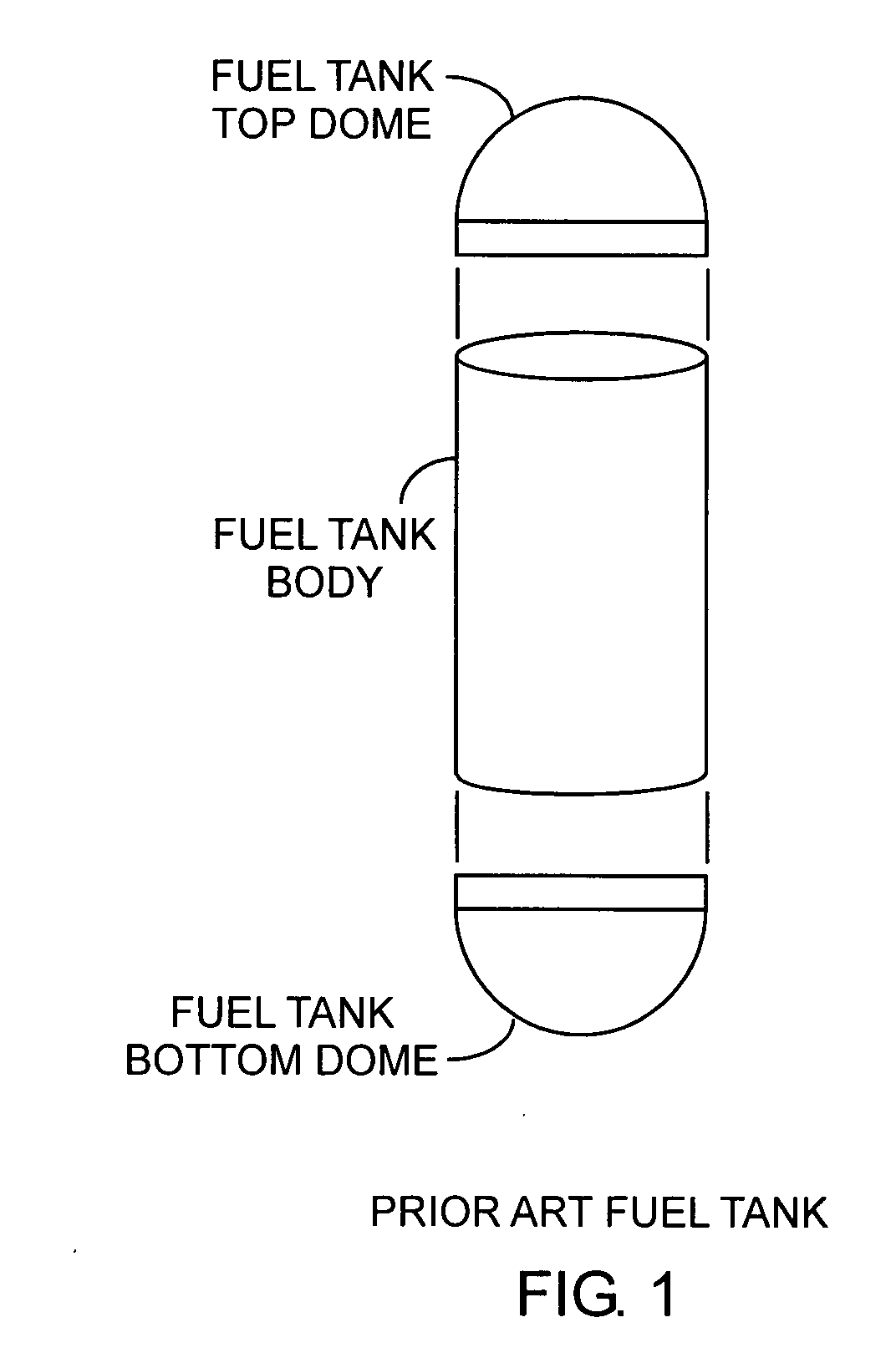
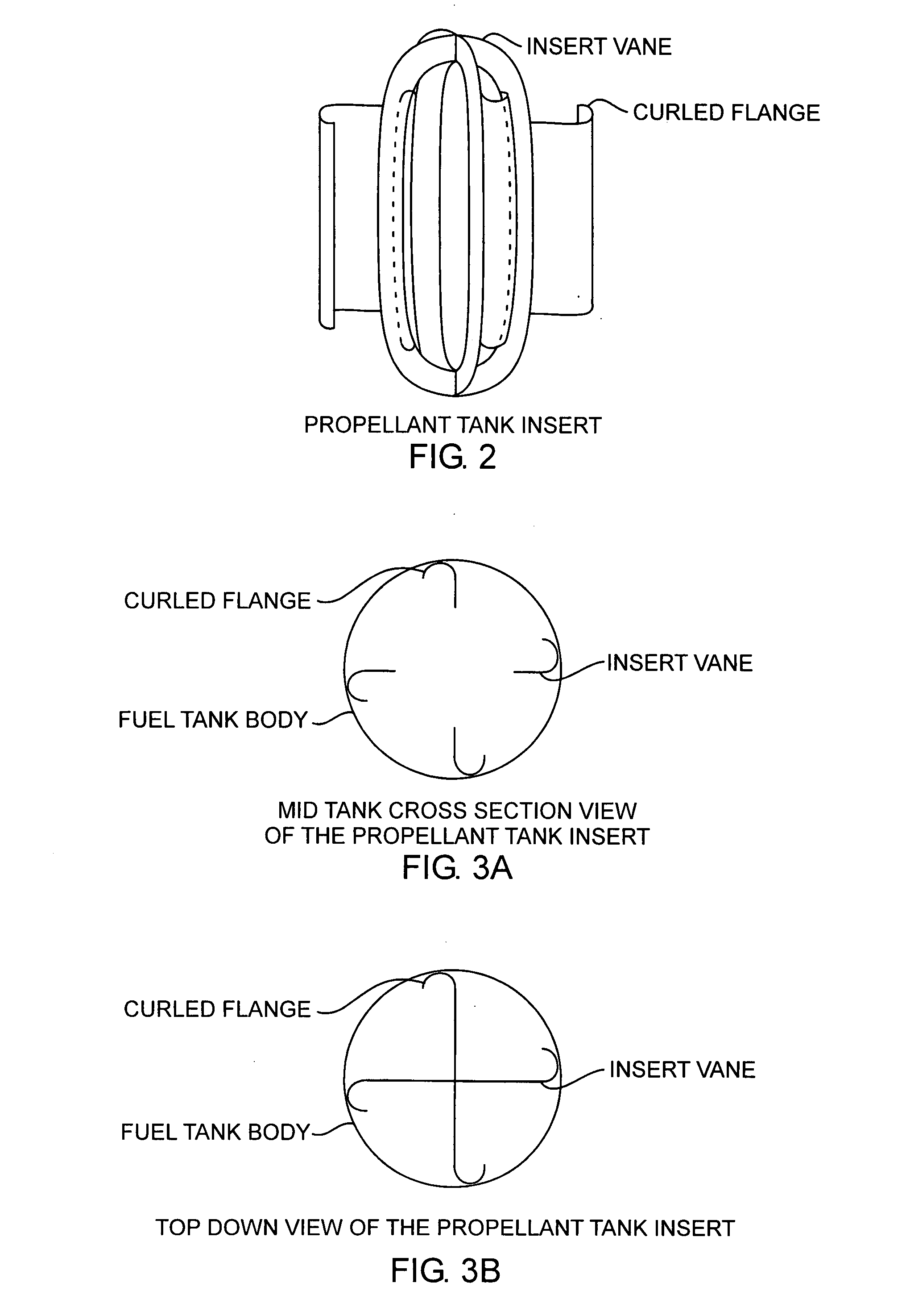
[0016]An embodiment of the invention is described with reference to the figures using reference designations as shown in the figures. Referring to FIGS. 1 and 2, a propellant tank insert includes two insert vanes coupled together at 90°. Each insert vane is an oval wick having an oval aperture. The oval perimeter of an insert vane matches an oval interior of a fuel tank. The insert vanes are attached to top and bottom dome ends of the fuel tank. The two insert vanes coupled at 90° form four half-oval portions. Each of the four half-oval portions has a curled flange extending outward from the perimeter of the four half-oval portions. The insert vanes are preferably wicks extending the entire length of the tank for maximum wicking.

[0017]Referring to all of the Figures, and more particularly to FIGS. 3A and 3B, the curled flanges are sized to make abutting contact with the interior of the tank along four respective four contact lines running vertically along the interior surface elonga...


PUM

PropertyMeasurementUnit
diameteraaaaaaaaaa
surface tension forcesaaaaaaaaaa
sizeaaaaaaaaaa

Abstract

A propellant management device comprising a plurality of insert vanes with respective outwardly extending curved flanges is disposed in a propellant tank with the curved flanges having mating contact along contacting lines on the interior of the tank as the insert vanes serves to wick fuel within the tank with reduced particulate generation within the tank for improved reliability and use of the propellant tank.

Description

STATEMENT OF GOVERNMENT INTEREST[0001]The invention was made with Government support under contract No. FA8802-04-C-0001 by the Department of the Air Force. The Government has certain rights in the invention.FIELD OF THE INVENTION[0002]The invention relates to the field of propellant tanks including tank wicks and particulate management devices. More particularly, the invention relates to an internal wick device that reduces particulate generation within a tank.BACKGROUND OF THE INVENTION[0003]Referring to FIG. 1, propellant fuel tanks have long been used. Fuel tanks are comprised of a fuel tank top dome, a fuel tank body, and fuel tank bottom dome. The body is a cylindrical body. Each of the domes typically includes a semispherical top and short cylindrical section. The two cylindrical sections are respectively mated to opposing ends of the cylindrical body. As such, the interior of the fuel tank defines an oval cavity in which fuel is disposed.[0004]Such a fuel tank suffers from t...

Claims


Application Information

Patent Timeline
Patent Type & Authority Applications(United States)
IPC IPC(8): F23D14/00
CPCF02K9/605F05D2300/133F05D2250/14F05D2250/71
Inventor LAU, KENNETH H.
Owner THE AEROSPACE CORPORATION
Why Eureka
Try Eureka