Preparation method of magnetic tunnel junction

A magnetic tunnel junction and crystallization technology, applied in the field of tunnel junction, can solve the problem of low TMR value of magnetic tunnel junction, and achieve the effect of improving spin filtration efficiency and TMR value, good read and write characteristics, and reducing particle pollutants

Inactive Publication Date: 2021-02-02
CETHIK GRP +1
View PDF11 Cites 0 Cited by
  • Summary
  • Abstract
  • Description
  • Claims
  • Application Information

AI Technical Summary

Problems solved by technology

[0005] The main purpose of the present invention is to provide a kind of preparation method of magnetic tunnel junction, to solve the problem that the TMR value of magnetic tunnel junction is on the low side in the prior art

Method used


Image

  • Preparation method of magnetic tunnel junction
  • Preparation method of magnetic tunnel junction
  • Preparation method of magnetic tunnel junction

Examples


preparation example Construction

[0029] As introduced in the background art, there is an urgent need to optimize the preparation process of the MTJ in the prior art, so as to solve the problem that the TMR value of the MTJ is low because MgO is used as a barrier layer. The inventors of the present invention have studied the above problems and proposed a method for preparing a magnetic tunnel junction, including the steps of forming a reference layer 10, a barrier layer 20 and a free layer 30, wherein the step of forming the barrier layer 20 includes : S1, using the radio frequency magnetron sputtering process to form the first magnesium oxide layer on the surface of the reference layer 10 or the free layer 30, as the crystallization inducing layer 210; S2, using the DC magnetron sputtering process and oxidation process on the surface of the crystallization inducing layer 210 The second magnesium oxide layer 230 is formed, and the preparation method further includes the step of performing a first heat treatment...

Embodiment 1

[0050] The preparation method of the magnetic tunnel junction provided in this embodiment includes the following steps:

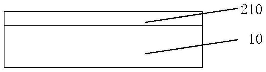
[0051] The first magnesium oxide layer is formed on the surface of the FeCoB reference layer 10 by radio frequency magnetron sputtering process, the thickness is 0.2nm, as the crystallization inducing layer 210, such as figure 1 As shown, the process conditions of the RF magnetron sputtering process include: 5mTorr, power 150W;

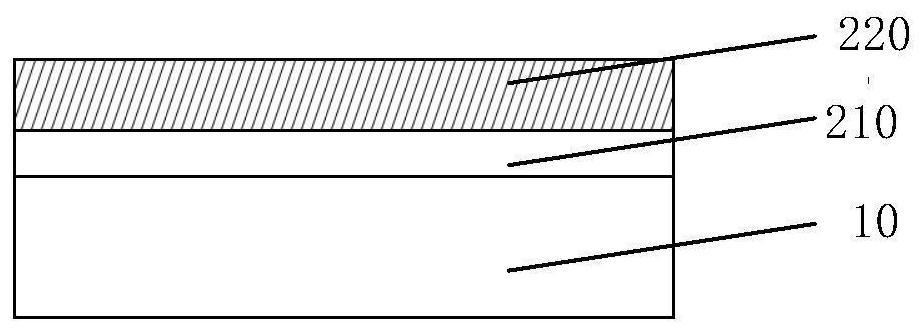
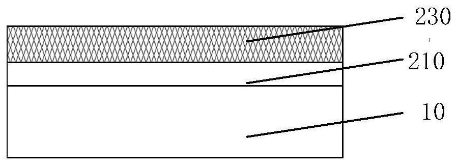
[0052] Magnesium metal is deposited on the crystallization inducing layer 210 by a DC magnetron sputtering process to form a magnesium metal layer 220, such as figure 2 As shown, the process conditions of the DC magnetron sputtering process include: the sputtering pressure is 10mTorr, the power is 150W, and then the magnesium metal layer 220 is oxidized in an oxygen atmosphere to form a second magnesium oxide layer 230 with a thickness of 0.4nm ,Such as image 3 As shown, the crystallization inducing layer 210 and the second mag...

Embodiment 2

[0056] The preparation method of the magnetic tunnel junction provided in this embodiment includes the following steps:

[0057] The first magnesium oxide layer is formed on the surface of the FeCoB reference layer 10 by radio frequency magnetron sputtering process, the thickness is 0.3nm, as the crystallization inducing layer 210, such as figure 1 As shown, the process conditions of the RF magnetron sputtering process include: 10mTorr, power 300W;

[0058] Magnesium metal is deposited on the crystallization inducing layer 210 by a DC magnetron sputtering process to form a magnesium metal layer 220, such as figure 2 As shown, the process conditions of the DC magnetron sputtering process include: the sputtering pressure is 20mTorr, the power is 200W, and then the magnesium metal layer 220 is oxidized in an oxygen atmosphere to form a second magnesium oxide layer 230 with a thickness of 0.5nm ,Such as image 3 As shown, the crystallization inducing layer 210 and the second ma...


PUM

PropertyMeasurementUnit
thicknessaaaaaaaaaa
thicknessaaaaaaaaaa
thicknessaaaaaaaaaa

Abstract

The invention provides a preparation method of a magnetic tunnel junction. The preparation method comprises the steps of: forming a reference layer, a barrier layer and a free layer. The step of forming the barrier layer comprises the following steps of: S1, forming a first magnesium oxide layer on the surface of the reference layer or the free layer by adopting a radio frequency magnetron sputtering process to serve as a crystallization induction layer; and S2, forming a second magnesium oxide layer on the surface of the crystallization induction layer by adopting a direct-current magnetron sputtering process and an oxidation process. The preparation method further comprises the step of carrying out first heat treatment on the reference layer, the barrier layer and the free layer together. The first magnesium oxide layer formed by deposition through the radio frequency magnetron sputtering process is usually in a polycrystalline state and has certain (001) orientation in a just deposited state, and therefore, when the first magnesium oxide layer is used as the crystallization induction layer, a (001) MgO structure can be formed on the surface of the crystallization induction layer, the reference layer, the barrier layer and the free layer have (001) orientation, and the spin filtering efficiency and the TMR value of the MTJ are improved; and good read-write characteristics areobtained.

Description

technical field [0001] The invention relates to the technical field of tunnel junctions, in particular to a method for preparing a magnetic tunnel junction. Background technique [0002] Magnetic Random Access Memory (MRAM) uses the magnetoresistance effect of materials to store data, and its core storage unit is a magnetic tunnel junction (MTJ). The MTJ device is mainly composed of a pinning layer, an insulating barrier layer and a free layer. The pinning layer is also called a reference layer. Its magnetization direction remains unchanged, and only the magnetization direction of the free layer is changed to make it in the same direction as the pinning layer or reverse. MTJ devices rely on quantum tunneling to allow electrons to pass through insulating barrier layers. The tunneling probability of polarized electrons is related to the relative magnetization directions of the pinned layer and the free layer. When the magnetization direction of the pinned layer is the same ...

Claims


Application Information

Patent Timeline
Patent Type & Authority Applications(China)
IPC IPC(8): H01L43/12
CPCH10N50/01
Inventor 蒋信简红
Owner CETHIK GRP
Why Eureka
Try Eureka