Metal working fluid decontamination apparatus

a technology of working fluid and metal working fluid, which is applied in water treatment multi-stage treatment, water/sewage multi-stage treatment, separation process, etc., can solve the problems of reducing the effectiveness of metal working fluid, contaminating metal working fluid with a range of contaminants, and affecting the health of machine operators

Pending Publication Date: 2022-07-07
WILDS IVAN MARK +1
View PDF0 Cites 0 Cited by
  • Summary
  • Abstract
  • Description
  • Claims
  • Application Information

AI Technical Summary

Benefits of technology

[0015]a decontaminator for reducing contamination in the metal working fluid;
[0019]Possibly, the decontaminator comprises a filter arrangement, to reduce particulate contamination in the metal working fluid.
[0025]Possibly, the decontaminator comprises an ultraviolet (UV) light treatment arrangement, possibly to reduce microbial contamination and possibly to reduce endotoxins in the metal working fluid.
[0057]a decontaminator for reducing contamination in the metal working fluid;

Problems solved by technology

Over a period of time, the metal working fluid becomes contaminated by a range of contaminants, including metal particulates, air borne particulates, tramp oil and microbial contaminants such as bacteria.
The contaminants present a risk to the health of the machine operatives and also reduce the effectiveness of the metal working fluid.
In practice, microbial contamination is of most concern, as it presents a serious health risk, and causes unpleasant odours.
Thus, microbial contamination results in poor and potentially unsafe working conditions for the operatives.
Conventionally, metal working fluid contamination requires that metal working fluids are replaced on a regular, periodic basis as they become contaminated, entailing disposal costs for the user.
However, the biocides become depleted over time and increased use of biocides itself presents a health, safety and environmental concern.
In addition, regulatory changes may limit the availability of biocides as tank side additives.

Method used


Image

  • Metal working fluid decontamination apparatus
  • Metal working fluid decontamination apparatus

Examples


Embodiment Construction

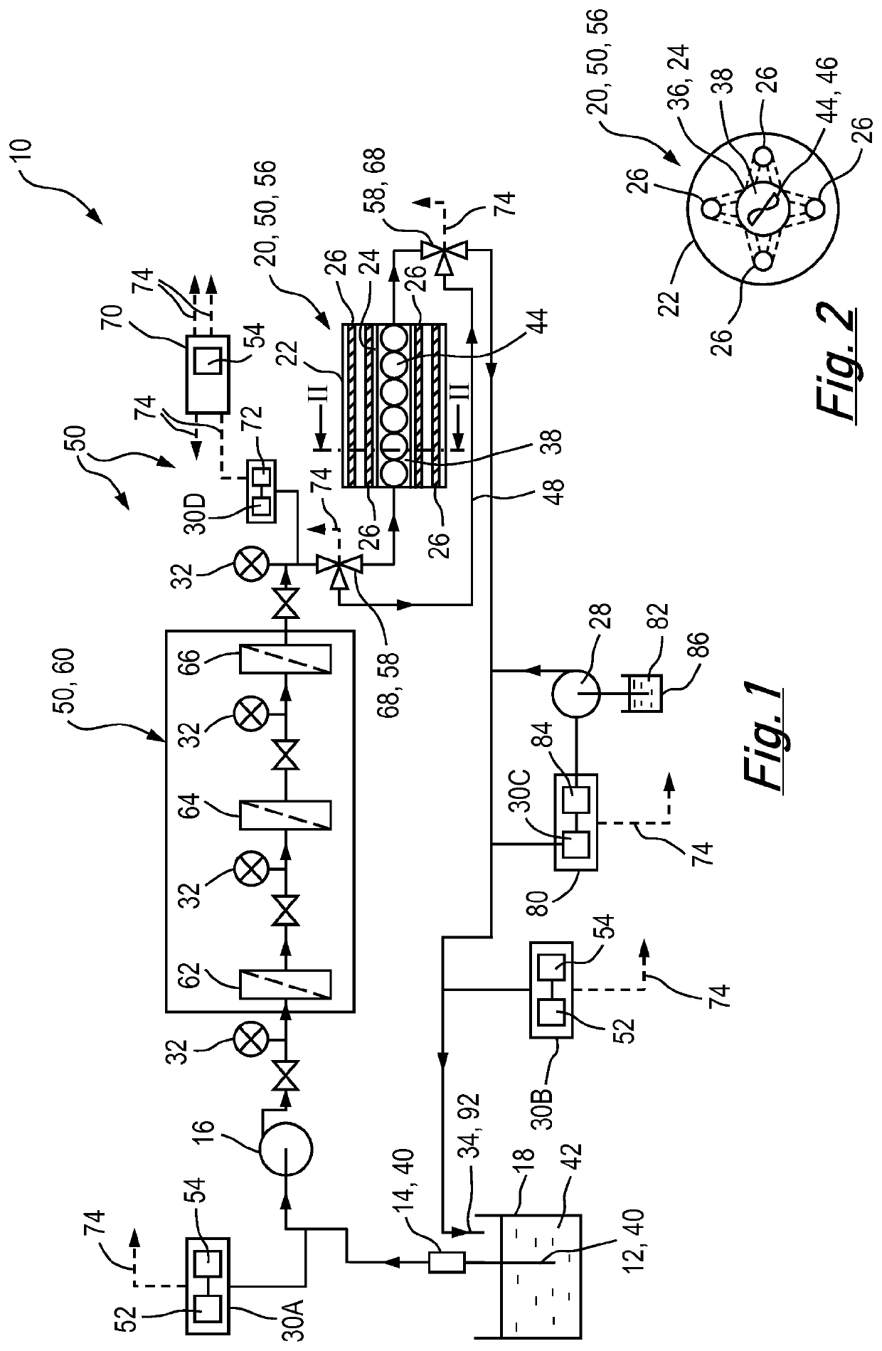
[0065]FIGS. 1 and 2 show metal working fluid decontamination apparatus10. The apparatus 10 includes: an intake arrangement 40 for metal working fluid 42; a pump 16 for providing, in use, flow pressure to the metal working fluid 42; a decontaminator 50 for reducing contamination in the metal working fluid 42; and an outlet arrangement 34 for the metal working fluid.

[0066]The metal working fluid 42 is a fully synthetic metal working fluid, which comprises water and a water soluble synthetic concentrate which does not comprise oil. The metal working fluid 42 is non-combustible.

[0067]In one example, the metal working fluid 42 could comprise, in a fresh (i.e. unused) condition, no more than 10% by weight of the synthetic concentrate, and could comprise no less than 2% by weight of the synthetic concentrate in the fresh condition. In another example, the metal working fluid 42 could comprise, in the fresh condition, no more than 7% by weight of the synthetic concentrate, and could compris...


PUM

PropertyMeasurementUnit
wavelengthaaaaaaaaaa

Abstract

Metal working fluid decontamination apparatus (10) includes: an intake arrangement (40) for metal working fluid (42); a pump (16) for providing, in use, flow pressure to the metal working fluid (42); a decontaminator (50) for reducing contamination in the metal working fluid (42); and an outlet arrangement (34) for the metal working fluid. The metal working fluid (42) is a fully synthetic metal working fluid, which comprises water and a water soluble synthetic concentrate which does not comprise oil.

Description

BACKGROUND OF THE INVENTION1. Field of the Invention[0001]The present invention relates to metal working fluid decontamination apparatus.2. The Prior Art[0002]Metal working fluids are fluids which are used to lubricate and / or cool metal work pieces in metal working operations such as machining, cutting and forming.[0003]Conventionally, metal working fluids are formed by adding a concentrate to water. The most commonly used concentrates comprise oil and performance additives including an emulsifier, and when added to water form a semi translucent or milky white emulsion.[0004]One alternative to a conventional metal working fluid is a fully synthetic metal working fluid, which comprises water and a water soluble synthetic concentrate which does not contain oil. Examples of fully synthetic metal working fluids include water-miscible metal working fluids.[0005]In use, a tank of the metal working fluid is located on or close by to the machine performing the metal working operation. The m...

Claims


Application Information

Patent Timeline
Patent Type & Authority Applications(United States)
IPC IPC(8): A61L2/02A61L2/10A61L2/26C10M177/00C10M173/02C09K5/20C09K15/00C11D7/50C02F9/00C02F1/00B01D36/02
CPCA61L2/022A61L2/10A61L2/26C10M177/00C10M173/02C09K5/20C10N2040/22C11D7/50C02F9/00C02F1/008B01D36/02A61L2202/14A61L2202/11C09K15/00C02F1/325C02F2103/16C02F2201/328C02F2201/3227C02F1/66C02F1/004C02F2209/001C02F2209/003C02F2209/06C02F2303/04C02F2301/08C02F2201/006A61L2202/17Y02A20/152Y02P70/10B01D35/02C10M173/00C10M175/00C10M175/0058C10M175/0066C02F2209/03C02F2301/024C02F2301/043C10N2040/08C10N2040/24C10N2070/00
Inventor WILDS, IVAN MARKWILDS, PAUL RODGER GERALD
Owner WILDS IVAN MARK
Why Eureka
Try Eureka