Device and method for tissue retraction in spinal surgery

a tissue retraction and spinal surgery technology, applied in the field of temporary inserting surgical devices, can solve the problems of significantly elevating the risk of injury to adjacent soft tissue structures, prone to undesirable shifting or migrating of the retractor system within the wound, and currently available retractor systems can be considered less than completely satisfactory, so as to maintain soft tissue retraction, less manipulation, and less damage. the effect of damag

Inactive Publication Date: 2009-03-19
TRANS CORP
View PDF99 Cites 85 Cited by
  • Summary
  • Abstract
  • Description
  • Claims
  • Application Information

AI Technical Summary

Benefits of technology

[0008]Conventional techniques in spinal fusion surgery typically make use of a stabilizing bone plate that is applied after tissue removal and after the insertion of a repair device. Since stabilizing bone plates are applied toward the end of the procedure, currently available soft tissue retractor systems cannot interact with these bone plates. However, as disclosed in U.S. patent application Ser. No. 11 / 855,124 of Lowry (entitled “Implantable bone plate system and related method for spinal repair”, filed on Sep. 13, 2007, and incorporated herein by this reference), a permanently implantable bone plate may be placed at a surgical site prior to substantial removal of tissue and prior to the insertion of a repair device. The invention now summarized here is directed toward a surgical device that includes a bone plate that is implanted before surgery, and which supports retractor blades for the purpose of maintaining soft tissue retraction during surgery. Embodiments of the inventive tissue retraction system require less manipulation during surgery than do currently available spinal retractor systems, thus placing collateral soft tissue at a lesser risk of damage, and generally improving the efficiency and safety of the surgical procedure.

Problems solved by technology

Currently available retractor systems are prone to undesirable shifting or migrating within the wound.
Consequently, currently available retractor systems can be considered less than completely satisfactory for several reasons.
For example, the field of view and working area within the surgical wound can be restricted by encroaching retractor devices and soft tissue, and they require frequent adjustment and repositioning during the surgery, significantly elevating the risk of injury to adjacent soft tissue structures with each adjustment and unnecessarily prolonging the procedure.

Method used


Image

  • Device and method for tissue retraction in spinal surgery
  • Device and method for tissue retraction in spinal surgery
  • Device and method for tissue retraction in spinal surgery

Examples


embodiment 300

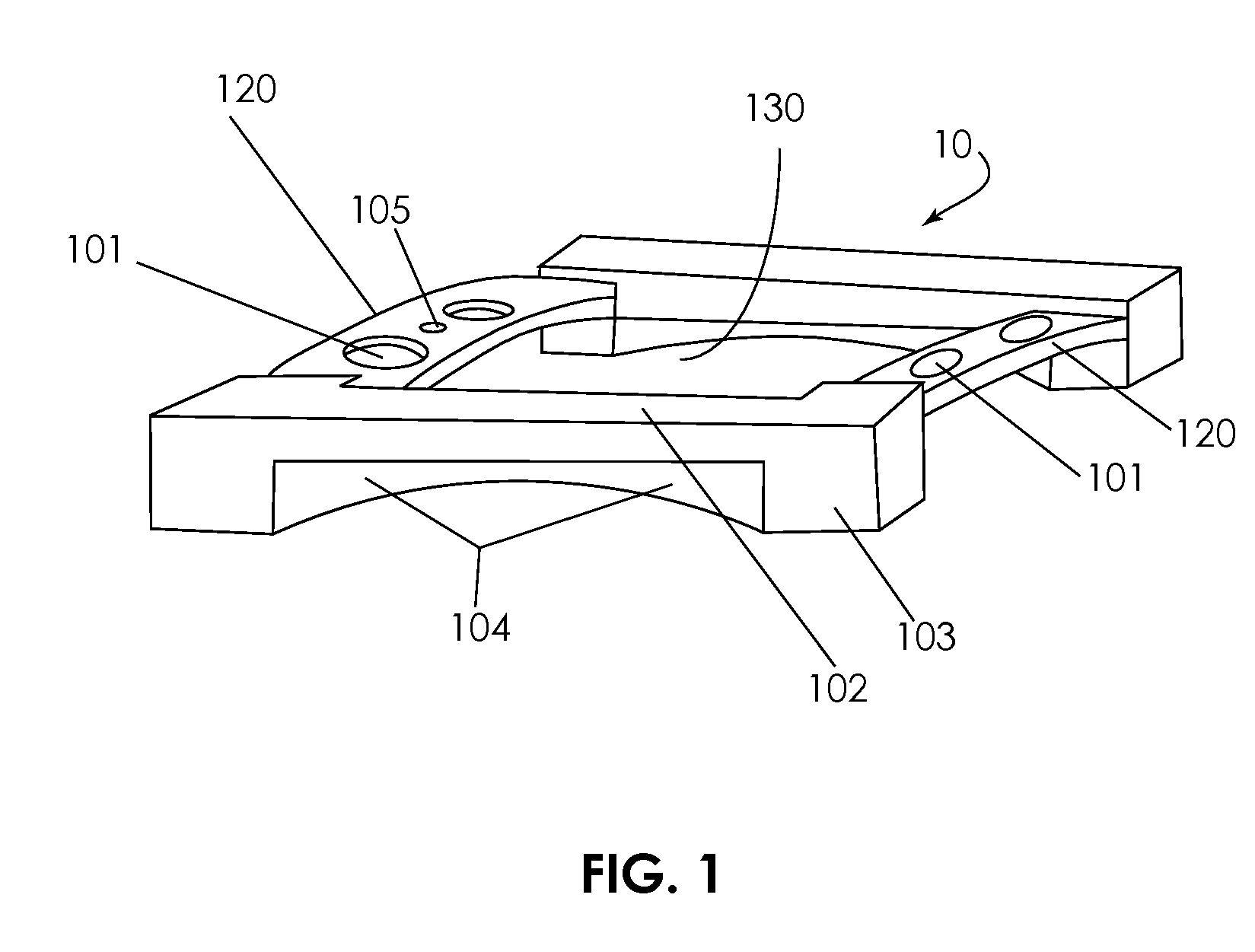
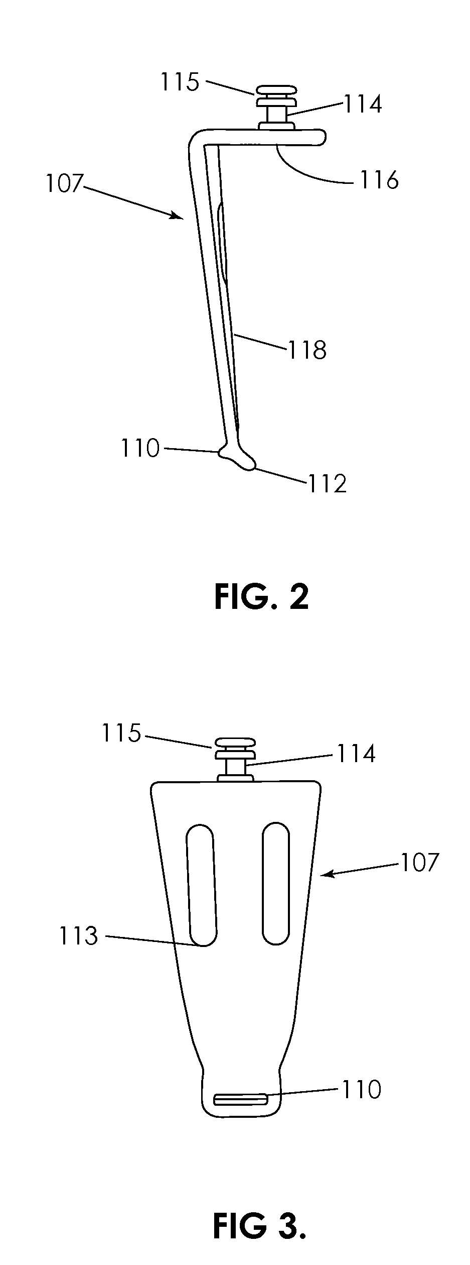
[0046]FIG. 7 is a top plan view of two retractor blades 107 outwardly spread and a bone plate 10 there between. The view shows the interaction of protrusions 110 of the retractor blades with side wall depressions on the bone plate 10 in situ, surrounded by retracted soft tissue 30. The impinging force of the soft tissue stabilizes the engagement between the retractor blade and the bone plate. In some embodiments, the respective positions of the protrusions 110 on the retractor blades 107 and the depressions 104 on plate 10 may be reversed. Alternatively, other inter-engaging features may be employed instead of the exemplary protrusions and depressions to allow retractor blades to temporarily and pivotably engage with plate. For example, a curved tongue may be used instead of protrusion 110, and a mating slot through plate 10 may be used instead of depression 104. The upper aspect or headplate 116 of retractor blades 107 can be seen engaging an angular adjustment mechanism 200. (Deta...

embodiment 108

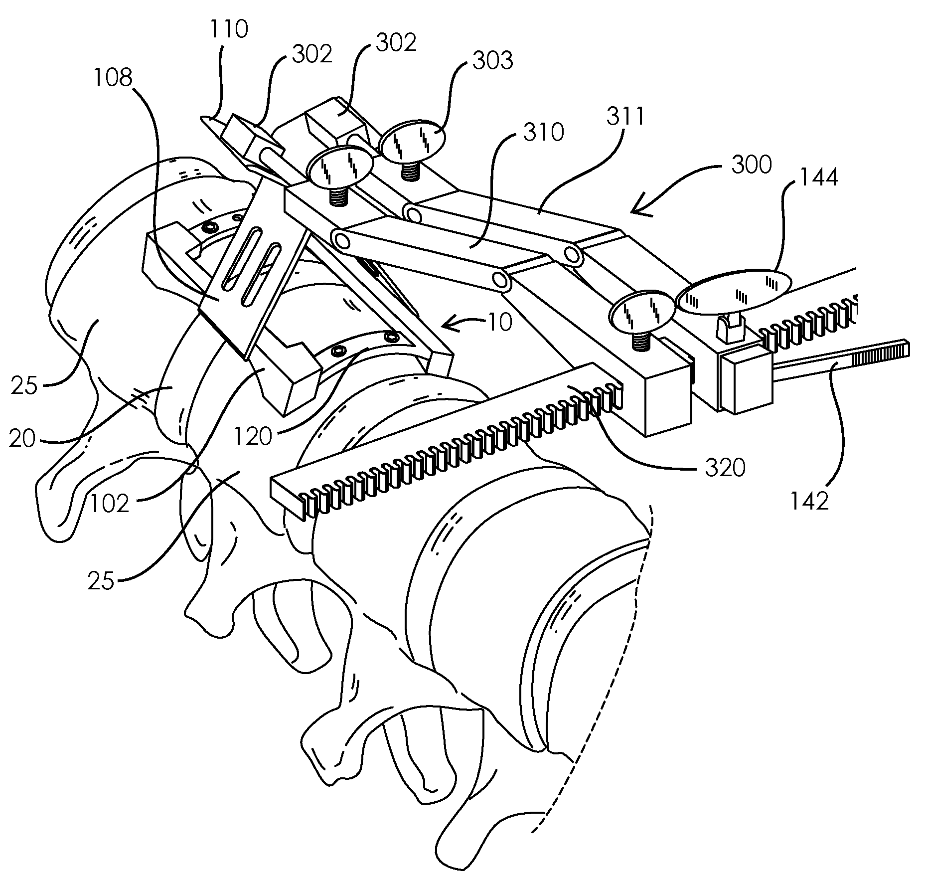
[0048]FIG. 8 shows a perspective view of an implanted bone plate 10. FIG. 9 shows a perspective view of the implanted bone plate 10 as in FIG. 8, with two retractor blades 108 now pivotably engaging the bone plate at their lower aspect 109 and pivotably engaging an adjustment mechanism 300 at their upper aspect 110. The bone plate is implanted on vertebral bodies 25 overlaying intervertebral disc 20. The blades are shown in an upwardly convergent configuration, as they would be prior to retracting adjacent soft tissue (not shown). The upper aspect 110 of the retractor blades 108 shown here differ compared to the upper portion of retractor blades 107 as shown in FIGS. 2-6, in that the embodiment 108 does not have an extension element 115 on the centrally-mounted post 114. The broad angled upper aspect 110 of retractor blade 108 is engageable with a pivotable engagement feature 302 of adjustment mechanism 300. This form of pivotable engagement between a retractor blade and an adjustme...


PUM


Abstract

The invention relates to a system and methods for retracting soft tissue during spinal repair or reconstruction procedures, particularly procedures within intervertebral sites of degenerated discs and associated neural compression. A retractor system includes an implantable bone plate, two or more retractor blades, the bone plate and retractor blades being mutually engageable; and a mechanism to adjust the retractor blade relative to the bone plate. In some embodiments, the retractor system may be applied to span more than one intervertebral space. An implanted retractor system provides an aperture for a clear operating field, and protects collateral tissue. A method for retracting soft tissue to facilitate spinal surgery includes securing a bone plate to adjacent vertebral bodies, engaging one or more retractor blades to the bone plate; and adjusting the angular position of the retractor blade relative to the bone plate so as to retract tissue lying external to the bone plate.

Description

CROSS REFERENCE TO RELATED APPLICATIONS[0001]This application claims priority to U.S. Provisional Patent Application No. 60 / 972,199 of Lowry et al., entitled “Device and method for tissue retraction in spinal surgery”, as filed on Sep. 13, 2007.FIELD OF THE INVENTION[0002]The present invention relates to temporarily-inserted surgical devices that engage a surgically implanted device already in place. More particularly, such a temporarily inserted device may engage an implanted vertebral stabilizing bone plate for purposes of maintaining soft tissue retraction during spinal surgery to facilitate the surgery and to protect the tissue from accidental injury.INCORPORATION BY REFERENCE[0003]All publications, patents and patent applications mentioned in this specification are herein incorporated by reference to the same extent as if each individual publication, patent or patent application was specifically and individually indicated to be incorporated by reference.[0004]In particular, U.S...

Claims


Application Information

Patent Timeline
Patent Type & Authority Applications(United States)
IPC IPC(8): A61B17/58
CPCA61B17/02A61B17/80A61B17/0206
Inventor LOWRY, DAVIDO'FARRELL, DESMONDTUINSTRA, SCOTTVELDMAN, ROGER
Owner TRANS CORP
Why Eureka
Try Eureka