Unlock instant, AI-driven research and patent intelligence for your innovation.

Protection control measurement system

a measurement system and control technology, applied in the direction of speed/acceleration/shock measurement, emergency protective circuit arrangement, instruments, etc., can solve the problems of hardware scale being larger than is necessary, video data transmitted and received is video data, and is not protection, control, or measurement data. , to achieve the effect of improving the operation accuracy of protection and control, high-efficiency protection control, and simplifying the configuration of measurement terminals

Inactive Publication Date: 2009-03-19
KK TOSHIBA
View PDF7 Cites 15 Cited by
  • Summary
  • Abstract
  • Description
  • Claims
  • Application Information

AI Technical Summary

Benefits of technology

[0012]This invention is proposed in order to resolve the above problem, and has as an object the provision of a protection control measurement system, with excellent economy and maintainability, which collects protection control measurement data via a communication network from a plurality of terminals, positioned in transformer substations, electric power plants, incoming transfer installations, and similar, which acquire electric quantities.
[0013]In order to attain the above object, a protection control measurement system of this invent, comprising measurement terminals which acquire electric quantities from an electric power system and electrical installations, a parent station device having arithmetic operation means for performing protection and control or measurement processing based on the electric quantities, and a communication network connecting the parent station device with at least one measurement terminal, is characterized in that the measurement terminals each comprises real-time transmission means for transmitting the electric quantities to the parent station device within a prescribed time, and message transmission means for transmitting to the parent station device, as setting values, correction coefficients to improve the operation accuracy of the protection and control or measurement processing, the transmission priority of the message transmission being lower than that of the real-time transmission; the real-time transmission means transmits the electric quantities within a prescribed time with higher priority than the message transmission over the communication network; the message transmission means transmits the setting values within a prescribed time after transmission of the electric quantities over the communication network; and the arithmetic operation means performs correction in which the electric quantities received from the real-time transmission means are corrected using the setting values received from the message transmission means, and calculates the input electric quantities.

Problems solved by technology

Specifically, in Japanese Patent Application Laid-open No. 2005-124206, communication means are proposed in which priority rights are assigned to real-time data, and in addition a communication protocol is applied for collision avoidance; but as explained above, the real-time data which is transmitted and received is video data, and is not protection, control, or measurement data.
Hence when the technology of Japanese Patent Application Laid-open No. 2005-124206 or the technology of Japanese Patent Application Laid-open No. 2000-92109 is applied to a protection control measurement system, it may be possible to transmit electric quantity data and similar in real-time, but various setting values and other non-real-time data is also transmitted by real-time communication means, so that there is the cost-related problem that the hardware scale must be made larger than is necessary.

Method used


Image

  • Protection control measurement system
  • Protection control measurement system
  • Protection control measurement system

Examples


first embodiment

1. First Embodiment

[1.1 Configuration]

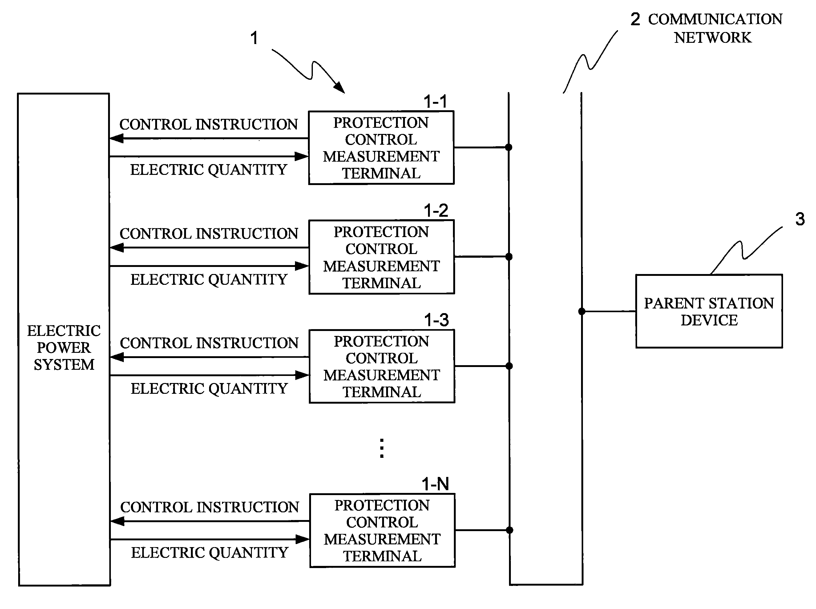
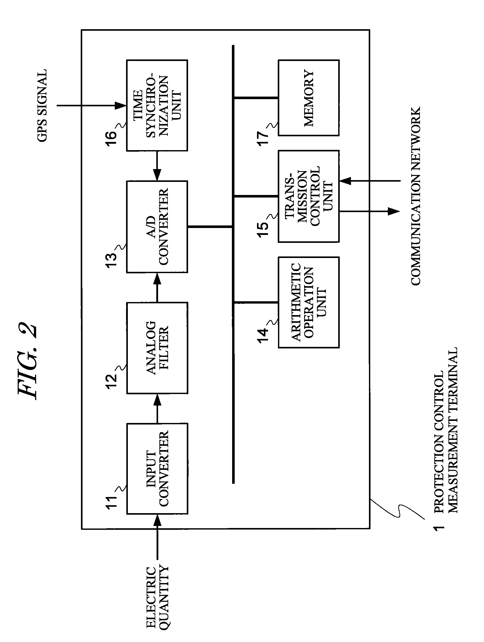
[0036]Next, the configuration of a protection control measurement system of this embodiment is explained below, referring to FIG. 1 through FIG. 3. FIG. 1 is a simplified diagram showing the relation between protection control measurement terminals 1, the communication network 2, and the parent station device 3 in this embodiment.

[0037]As shown in FIG. 1, in N protection control measurement terminals 1-1 to 1-N (where N?1), installed at the same or at different electric-supply stations, electric quantities, such as voltages and currents, for the electric power system (transmission lines, transformers, generators, and similar) are measured, and the electric quantities are transmitted over the communication network 2 to the parent station device 3.

[0038]In this parent station device 3, electric quantities sent from each of the protection control measurement terminals 1 are consolidated, protection operation, control operation and measurement opera...

second embodiment

2. Second Embodiment

[2.1 Configuration]

[0108]Next, the basic configuration of protection control measurement terminals 1 and a parent station device 3 of a second embodiment of the invention is explained, referring to FIG. 14. In this embodiment, the basic hardware configuration is the same as in the first embodiment, and an explanation is omitted.

[0109]A characteristic of the second embodiment is that arrival time-guaranteed transmission and message transmission between protection control measurement terminals 1 and the parent station device 3 over the communication network 2 can both be performed bidirectionally, and that setting values can be modified by the parent station device 3 via the communication network 2. Further, by outputting control instructions based on protection control measurement arithmetic operations to the protection control measurement terminals 1, the parent station device 3 can perform protection and control of an electric power system or similar from the pr...

third embodiment

3. Third Embodiment

[0117]Next, the configuration of protection control measurement terminals 1 and a parent station device 3 in a third embodiment of the invention is explained, referring to FIG. 15. In this embodiment, the basic configuration of the hardware is the same as in the first and second embodiments, and explanations are omitted.

[0118]A characteristic of the third embodiment, is that means comprised by the parent station device 3 is present within the protection control measurement terminals 1. Specifically, within the arithmetic operation processing unit 14 of each of the protection control measurement terminals 1 are provided, in addition to the setting vale transmission / reception means 14-2A and control instruction means 14-3 provided in the second embodiment, electric quantity arithmetic operation means 14-4, which multiplies electric quantity data received by the arrival time-guaranteed transmission means 15-1 by setting values received by the message transmission mea...


PUM


Abstract

This invention provides a protection control measurement system, with excellent economy and maintainability, which collects protection control measurement data via a communication network from a plurality of terminals which acquire electric quantities. In the protection control measurement terminal 1, electric quantity acquisition and transmission means 14-1 determines synchro-phasor quantities from electric quantity data and transmits the synchro-phasor quantities to arrival time-guaranteed transmission means 15-1. The arrival time-guaranteed transmission means 15-1 transmits in real-time the synchro-phasor quantities to the parent station device 3. Setting value transmission means 14-2 transmits setting value data to the message transmission means 15-2, which performs message transmission to the parent station device 3 over the communication network 2. In the parent station device 3, electric quantity arithmetic operation means 32-1 calculates electric quantities as close as possible to true values by multiplying received synchro-phasor quantities by setting value data. The protection control measurement arithmetic operation means 32-2 performs arithmetic operations for accident judgment for protection control measurement terminals 1 from the magnitudes of electric quantities and voltage phase differences.

Description

BACKGROUND OF THE INVENTION[0001]1. Field of the Invention[0002]This invention relates to a protection control measurement system which performs protection, control and measurement of an electric power system, and relates to a system with excellent economy and maintainability, which collects protection control measurement data using a communication network.[0003]2. Description of the Related Art[0004]Data communication means between terminals, installed in transformer substations, electric power plants, and similar of the prior art, have generally employed Ethernet (a registered trademark) and TCP / IP general-use protocols. In particular, as means for transmitting data reliably in a fixed length of time using Ethernet, communication means such as those described in Japanese Patent Application Laid-open No. 2005-124206 and Japanese Patent Application Laid-open No. 2000-92109 have been proposed.[0005]In Japanese Patent Laid-open Application No. 2005-124206, a method of transmission of ...

Claims


Application Information

Patent Timeline
IPC IPC(8): G01R15/00
CPCH02H7/261Y04S10/265Y02E60/728Y02E60/00Y04S10/00Y04S10/22Y02E40/70
Inventor SAKASHITA, HIRONORISEKIGUCHI, KATSUHIKOTAKEI, YOSHINORI
Owner KK TOSHIBA