Pillow Block Bearing for Shaft Driven Conveyor System with Self Aligning Feature

Active Publication Date: 2009-03-26
OCS INTELLITRAK
View PDF17 Cites 6 Cited by
  • Summary
  • Abstract
  • Description
  • Claims
  • Application Information

AI Technical Summary

Problems solved by technology

With prior art systems, if the gap is too wide, the canted driven wheels decouple from the rotating drive shafts when moving across the gap, resulting in a drop of propulsive for

Method used


Image

  • Pillow Block Bearing for Shaft Driven Conveyor System with Self Aligning Feature
  • Pillow Block Bearing for Shaft Driven Conveyor System with Self Aligning Feature
  • Pillow Block Bearing for Shaft Driven Conveyor System with Self Aligning Feature

Examples


Embodiment Construction

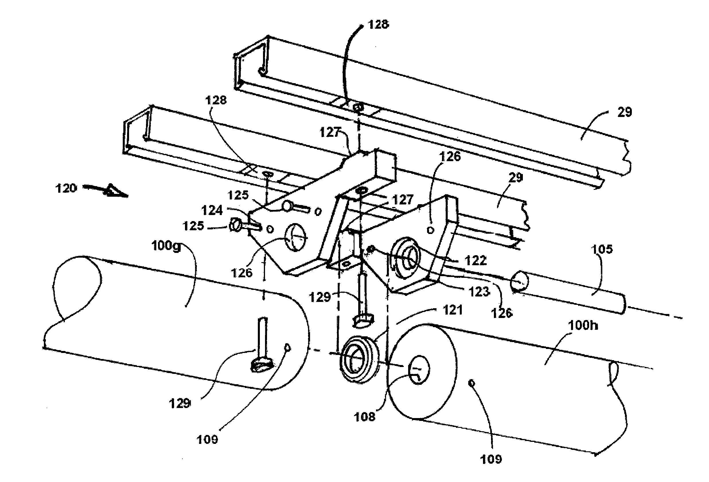
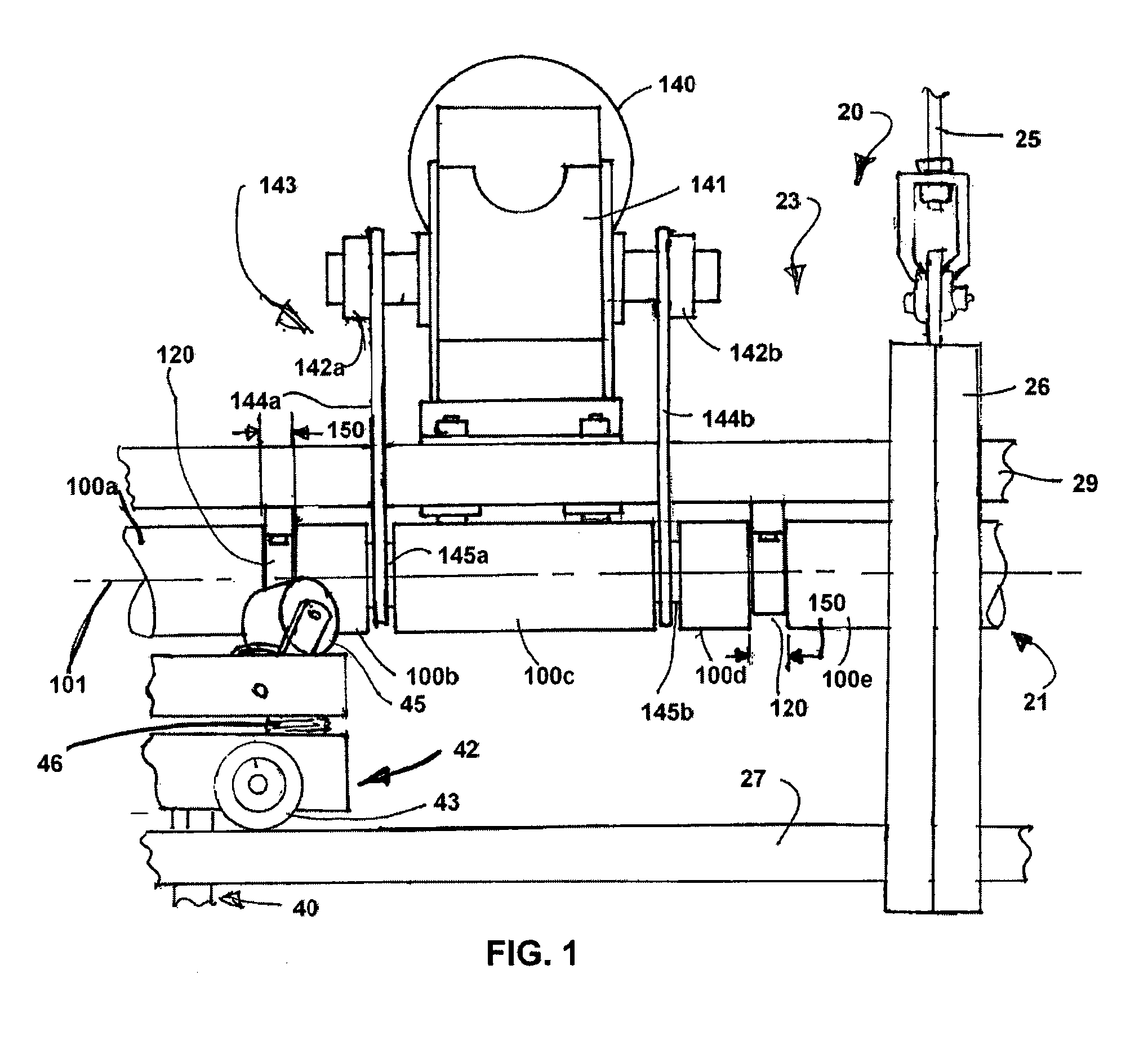
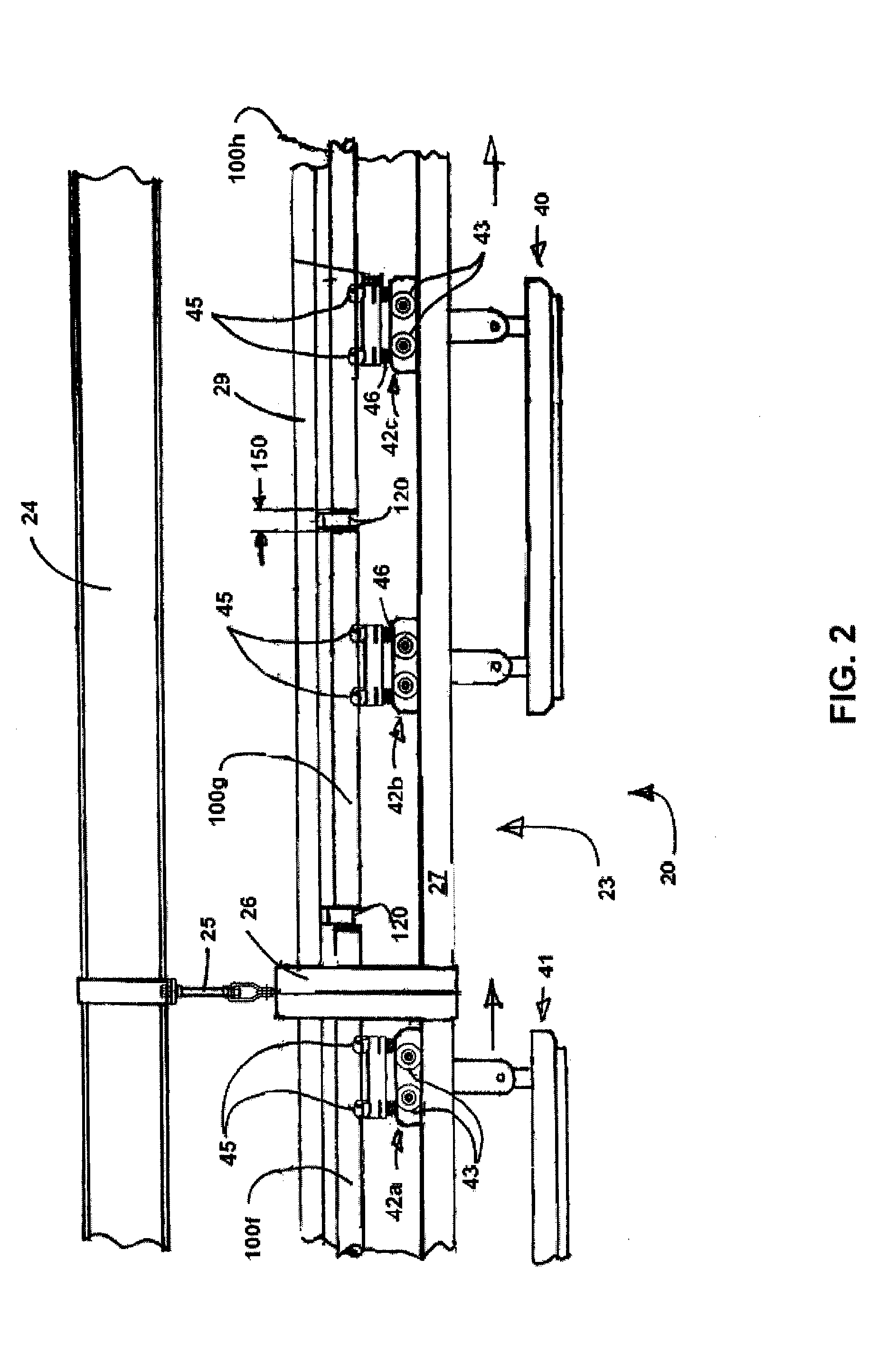
[0015]The following description of certain examples of the drive system should not be used to limit the scope of the present the drive system. Other examples, features, aspects, embodiments, and advantages of the of the drive system will become apparent to those skilled in the art from the following description, which is by way of illustration, one of the best modes contemplated for carrying out the drive system. As will be realized, the drive system is capable of other different and obvious aspects, all without departing from the drive system. Accordingly, the drawings and descriptions should be regarded as illustrative in nature and not restrictive. As shown in FIGS. 1 and 2, the overhead conveyor system 20 has one or more movable trolleys 40, 41 suspended therefrom to transport a load along a conveying path. The overhead conveyor system 20 has a rotating drive shaft 21 to propel the trolleys 40, 41 (FIG. 2), and a stationary frame or a support rail structure 23 to define the conv...


PUM


Abstract

A rotating shaft drive system is configured to propel a load along a conveying path of an overhead conveyor system. A stationary frame extends along the conveying path and supports the rotating shaft drive system. A movable carriage is suspended from the stationary frame and engages with a rotating shaft of the shaft drive system to propel the carriage and the load. The rotating shaft comprises a plurality of shaft segments supported pillow blocks at each end of the rotating shaft segments, and the pillow blocks create a gap between adjacent shaft segments. The movable carriage has at least one canted driven roller configured to engage with adjacent rotating shaft segments and to create a helical loci of tractional engagement that provides sufficient drive force to propel the carriage and the load along the conveying path. The drive system is further configured to provide continuous propulsion as the canted driven roller moves across the gap between adjacent shaft segments.

Description

CROSS REFERENCE TO RELATED APPLICATIONS [0001]The present application hereby claims the benefit of the provisional patent application of the same title, Ser. No. 60 / 974,311 filed on Sep. 21, 2007.FIELD OF THE PRESENT DRIVE SYSTEM [0002]The present drive system relates to a shaft driven conveyor system and relates, in general, to an overhead conveyor system with a carriage suspended therefrom and a rotating drive shaft having a plurality of inline shaft sections configured to drive the carriage along the overhead conveyor system and across gaps between the inline shaft sections.BACKGROUND [0003]In a conventional factory or distribution warehouse, it is desirable to move loads along a transporting path that is predominately horizontal, but which may also involve travel uphill, downhill, diversion between subpaths, and the like. These systems provide an overhead conveyor system with rotating drive shafts, a carriage that is supported by the drive shaft or by a fixed support rail, and a...

Claims


Application Information

Patent Timeline
IPC IPC(8): B65G35/00F16C19/00
CPCB65G35/063
Inventor TABLER, CHARLES PAUL
Owner OCS INTELLITRAK
Why Eureka
Try Eureka