
Positive pressure dust-proof structure for bearing

A dust-proof structure and bearing technology, which is applied in the direction of bearing components, shafts and bearings, bearing cooling, etc., can solve the problems of dust entering the interior of the bearing chamber, damaging the dust-proof structure, and accumulation, so as to reduce temperature, increase service life, and enhance Effect of cooling function

Pending Publication Date: 2018-03-23
Y & C ENGINE
View PDF0 Cites 3 Cited by
  • Summary
  • Abstract
  • Description
  • Claims
  • Application Information

AI Technical Summary

Problems solved by technology

[0004] Aiming at the deficiencies of the bearing dust-proof structure in the prior art, the purpose of the present invention is to provide a bearing positive pressure dust-proof structure with simple structure, dust-proof and heat dissipation functions, which is used to solve the problem of using the existing dust-proof structure for a period of time. Finally, the dust will still enter the bearing chamber through the gap, or the dust will accumulate on the edge of the dustproof structure and damage the dustproof structure

Method used


Image

  • Positive pressure dust-proof structure for bearing

Examples


Embodiment Construction

[0022] In the present invention, it should be understood that the terms "length", "width", "upper", "lower", "front", "rear", "left", "right", "vertical", "horizontal" ", "Top", "Bottom", "Inner", "Outer", "Clockwise", "Counterclockwise", "Axial", "Radial", "Circumferential" and other indications are based on The orientation or positional relationship shown in the drawings is only for the convenience of describing the present invention and simplifying the description, and does not indicate or imply that the referred device or element must have a specific orientation, be constructed and operated in a specific orientation, and therefore cannot be understood as Limitations on the Invention.

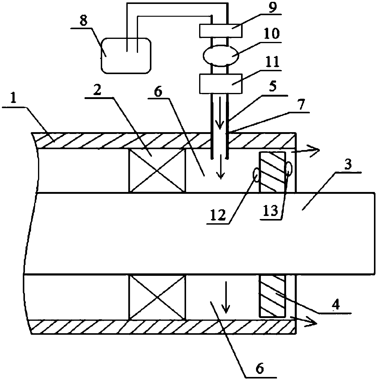
[0023] like figure 1 As shown, the arrows in the figure represent the flow direction of compressed air. A bearing positive pressure dustproof structure includes bearing housing 1, bearing 2, shaft 3 and spacer 4. Spacer 4 is fixedly sleeved on shaft 3. Spacer 4 It is an interference fit wi...


PUM


Abstract

The invention discloses a positive pressure dust-proof structure for a bearing. The positive pressure dust-proof structure comprises a bearing block, the bearing, a shaft and a spacer bush; the spacerbush is arranged on the shaft in an interference fit mode and is in clearance fit with the bearing block; a bearing chamber cavity is formed between the spacer bush and the bearing; a hole matched with a compressed air injection pipe is formed in the bearing block; and the length of the part, inserted into the bearing chamber cavity, of the compressed air injection pipe is larger than the lengthof a clearance between the spacer bush and the bearing block. According to the positive pressure dust-proof structure, the compressed air injection pipe communicates with the bearing chamber cavity, clean compressed air is injected into the bearing chamber cavity through the compressed air injection pipe at the relative pressure of 3kPa-5kPa and forms the positive pressure, the compressed air flows out of the clearance between the spacer bush and the bearing block due to the positive pressure existing in the bearing chamber cavity, dust, mud and the like can be prevented from entering the bearing chamber cavity due to the action of air flow, and therefore the purpose of dust prevention can be achieved; and the continuously flowing compressed air enhances the heat dissipation function of abearing chamber, and therefore the temperature of the bearing can be decreased, the operation environment of the bearing can be improved, and the service life of the bearing can be prolonged.

Description

technical field [0001] The invention belongs to the technical field of bearings, and in particular relates to a bearing positive pressure dustproof structure. Background technique [0002] Bearings are components that fix and reduce the friction coefficient of loads during mechanical transmission. It can also be said that when other parts move relative to each other on the shaft, they are used to reduce the friction coefficient during power transmission and maintain the center position of the shaft. fixed parts. Bearings are an important part of modern mechanical equipment. Its main function is to support the mechanical rotating body to reduce the friction coefficient of the mechanical load during the transmission process of the equipment. However, the bearing is a sensitive component to the working environment. Dust entering the bearing chamber will seriously damage the grease and lubrication of the bearing, which will lead to abnormal wear of the bearing and accelerate t...

Claims


Application Information

Patent Timeline
IPC IPC(8): F16J15/40F16C35/00F16C37/00
CPCF16C35/00F16C37/00F16J15/40
Inventor 于松林束铭宇齐玉龙
Owner Y & C ENGINE
Learn More