

Bearing Housing for a Conveyor Assembly and Bearing Assembly System
- Summary
- Abstract
- Description
- Claims
- Application Information
AI Technical Summary
Benefits of technology
Problems solved by technology
Method used
Image

Examples
Embodiment Construction
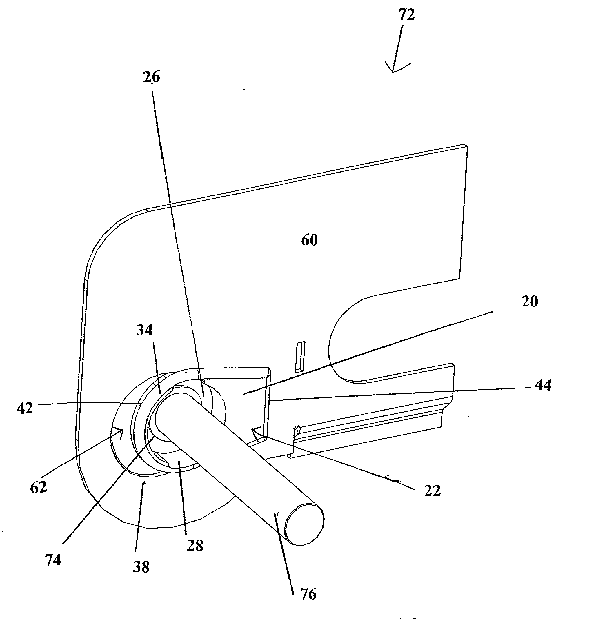
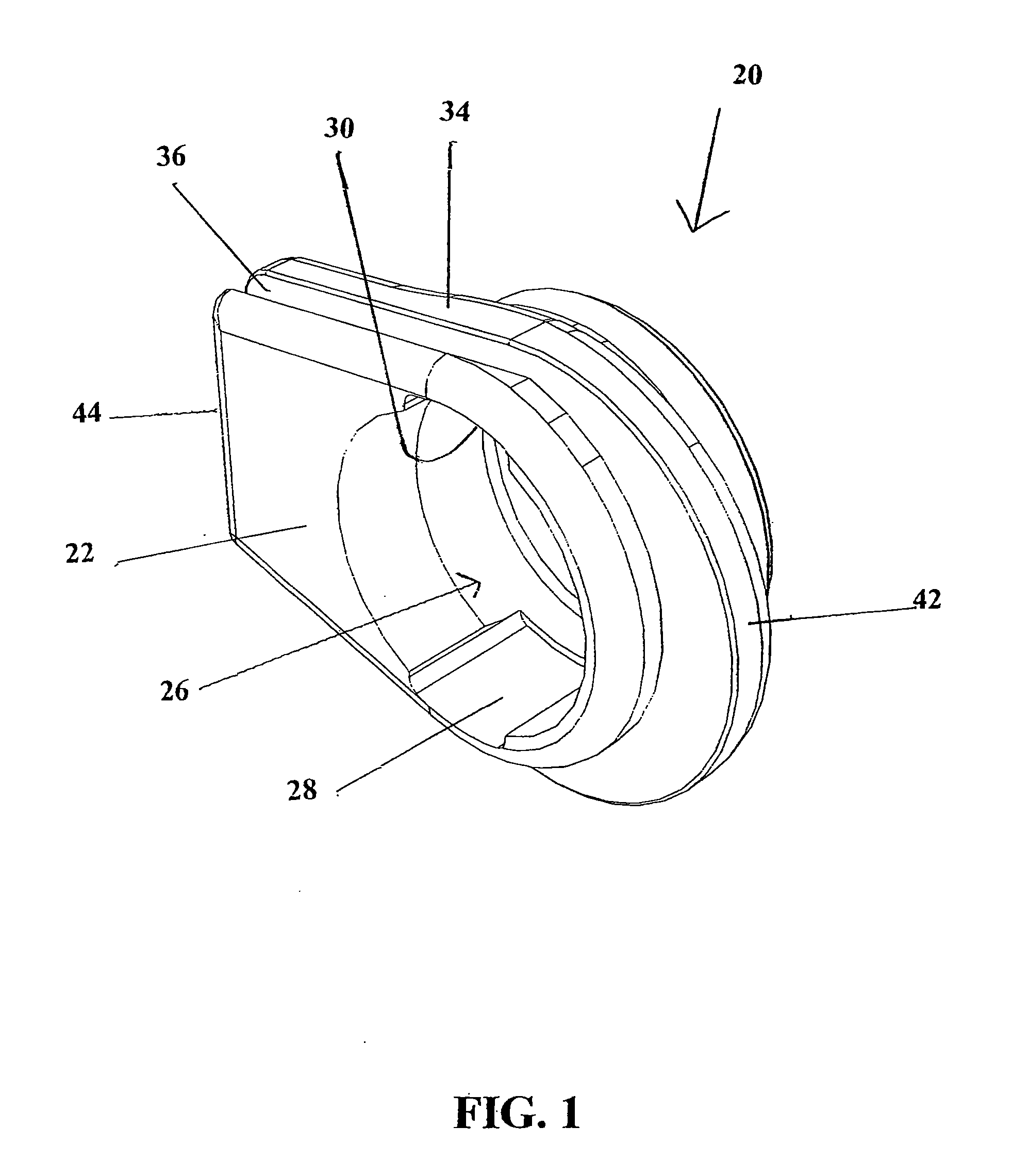
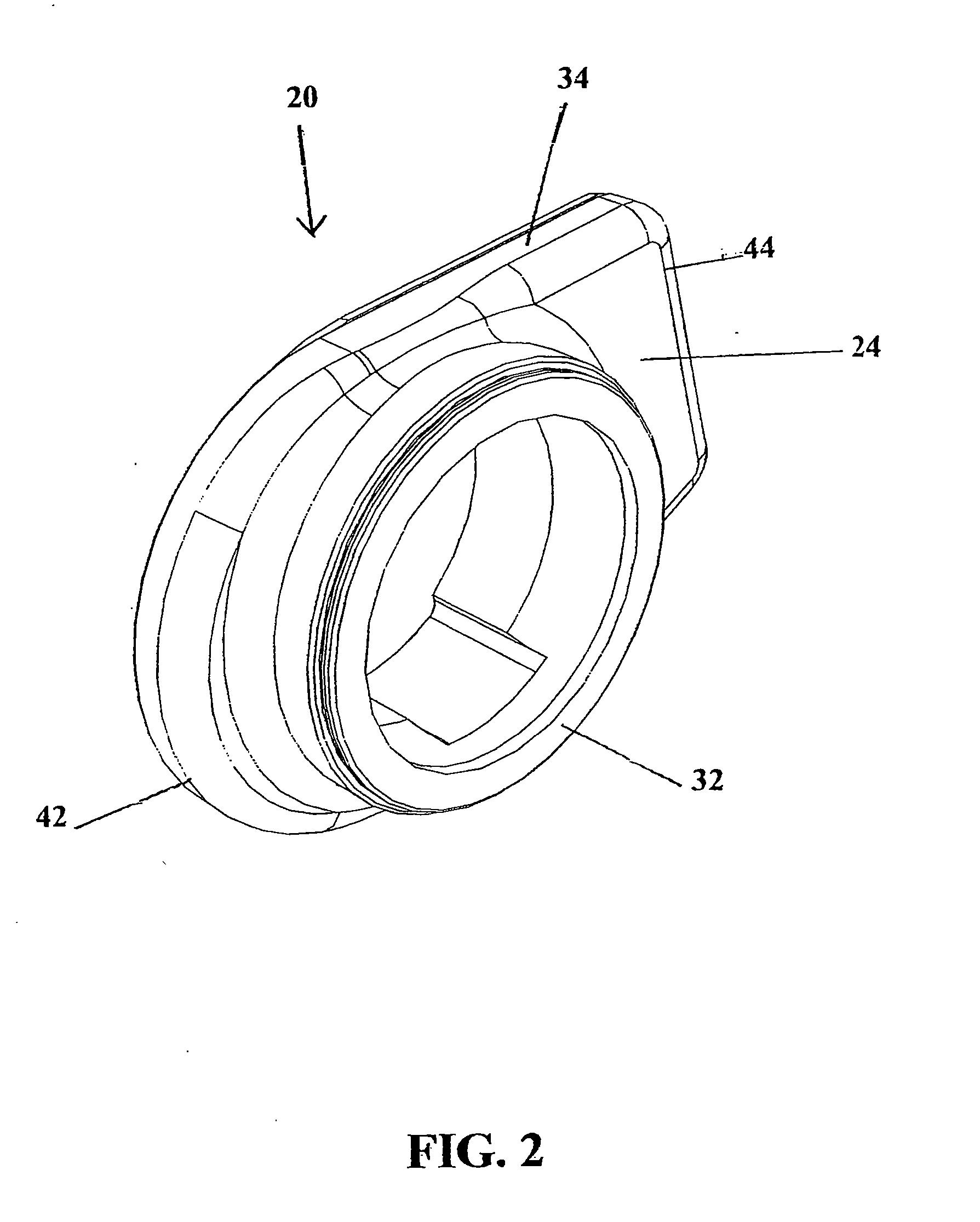
[0037] The present invention is embodied in a bearing housing for a conveyor assembly and a bearing assembly system. The bearing housing 20 comprises a device that is capable of being attached to the frame, rail, or panel 60 of the conveyor assembly without fasteners and at the same time, secures a bearing 74 therein without fasteners. As a result, the bearing and its housing are easy to assemble and disassemble and easy to clean, reducing down-time of the assembly and providing a means of maintaining a sanitary system.
[0038] While the disclosure herein is particularly described with regard to conveyors and industries where cleaning and sanitary conditions are important, it will be understood and apparent to those of skill in the art that the present invention has other applications where cleanliness or ease of cleaning, assembly and disassembly are important. The bearing housing of the present invention may be used or modified for use with any commercially available bearing or lik...
PUM
 Abstract
Description
Claims
Application Information