Tray flipper, tray, and method for parts inspection

a technology of parts inspection and flipper, which is applied in the field of machine vision, can solve the problems of affecting the throughput of the machine vision inspection system, requiring time and operator intervention, and prone to errors, so as to facilitate automated high-speed three-dimensional inspection, facilitate the operation of the machine, and reduce the chance of operator error

Inactive Publication Date: 2009-03-26
LEMAIRE CHARLES A
View PDF67 Cites 15 Cited by
  • Summary
  • Abstract
  • Description
  • Claims
  • Application Information

AI Technical Summary

Benefits of technology

[0025]Advantageously, the machine-vision-inspection system is capable of flipping trays of devices without operator intervention. The flipping device operates to reliably flip the trays of devices so that all portions of the devices within the trays are reliably inspected. The flipping device that facilitates automated high-speed three-dimensional inspection of objects in a manufacturing environment. The flipping mechanism is also easily accommodated as a station on an automated manufacturing line. Yet another advantage is that the inspection can take place automatically without the intervention of a human. This lessens the chance for operator error during the inspection process and aids in the throughput of the machine-vision-inspection system.

Problems solved by technology

Current vision-inspection systems have many problems.
Among the problems are assorted problems associated with current mechanical translation devices associated with vision-inspection systems.
Among the mechanical translation problems are that the trays of devices, such as trays of semiconductor chips, associated with current vision-inspection systems must be flipped by hand since both sides of the devices must be inspected.
Operator intervention requires time and may be prone to error.
Throughput of the machine-vision-inspection system may also be affected.
For example, if the operator is on break or otherwise unavailable, throughput of the machine-vision-inspection system suffers since the machine is stopped awaiting operator intervention.
As mentioned, errors can also occur as a direct result of operator intervention.
If the operator is interrupted while flipping the trays, the operator may forget the orientation of the devices or trays after the interruption.
In other words, due to the interruption, the tray carrying the devices may not be flipped.
In this event, more time is lost since the operator must now flip the unflipped trays.
This of course also negatively affects throughput of the machine-vision-inspection system.
At worst, the machine-vision-inspection system would not detect that the wrong side of the device (same side of the device previously inspected) was again being inspected.
The result would be far worse in that devices that would not pass the inspection would be shipped to customers or placed in larger devices shipped to customers.
If the products were not caught be a subsequent sampling or inspection, defective product may be shipped to a customer.
This of course is devastating in a world where product quality is constantly stressed by marketing executives.
Even a hint of less than top quality can devastate the market for a product.

Method used


Image

  • Tray flipper, tray, and method for parts inspection
  • Tray flipper, tray, and method for parts inspection
  • Tray flipper, tray, and method for parts inspection

Examples


Embodiment Construction

[0068]In the following detailed description of the preferred embodiments, reference is made to the accompanying drawings which form a part hereof, and in which are shown by way of illustration specific embodiments in which the invention may be practiced. It is to be understood that other embodiments may be utilized and structural changes may be made without departing from the scope of the present invention.

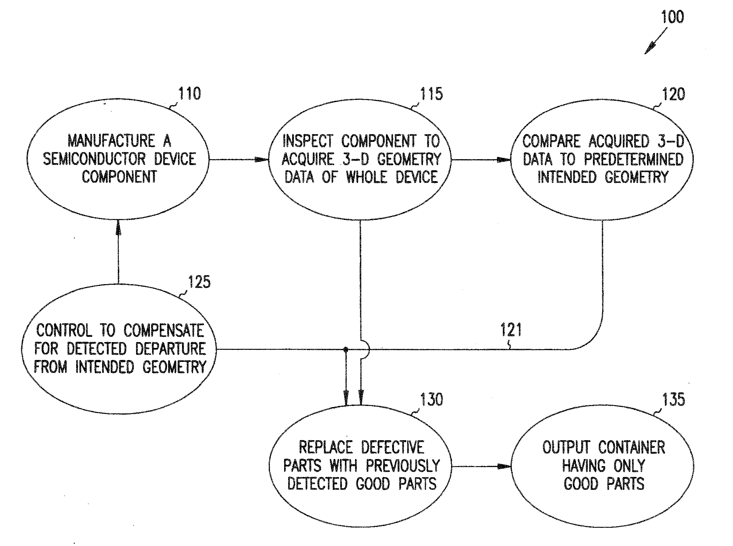
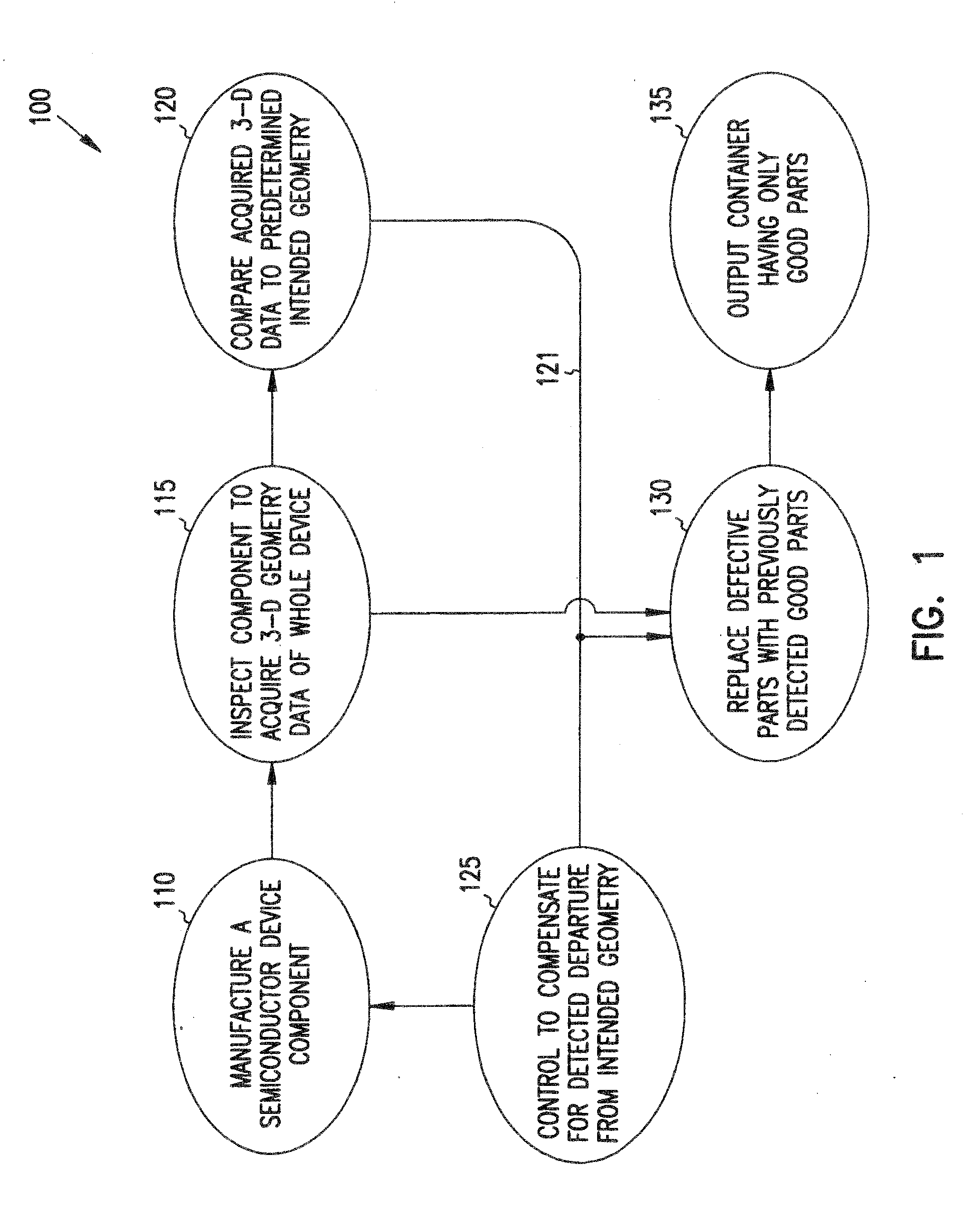
[0069]Machine-vision and optical-feature-recognition techniques can be used to distinguish parts that deviate from a predetermined intended aspect of an ideal device. In this description, a “device” is meant to be any device of manufacture or object, for example an integrated circuit package, electronic part, semiconductor, molded plastic part, aluminum wheel, gemstone or even an egg or strawberry, which can be inspected. Typically, according to the present invention, a manufacturing operation will use two-dimensional and three dimensional information acquired from inspection of t...


PUM


Abstract

Manufacturing lines include inspection systems for monitoring the quality of parts produced. Manufacturing lines for making semiconductor devices generally inspect each fabricated part. The information obtained is used to fix manufacturing problems in the semiconductor fab plant. A machine-vision system for inspecting devices includes a flipper mechanism. After being inspected at a first station, a tray-transfer device moves the tray from the first inspection station to a flipper mechanism. The flipper mechanism includes two jaws, a mover, and a rotator. The flipper mechanism turns the devices over and places the devices in a second tray so that another surface of the device can be inspected. A second tray-transfer device moves the second tray from the flipper to a second inspection station. The mover of the flipper mechanism removes the tray from the first inspection surface and places a tray at the second inspection surface.

Description

CROSS-REFERENCE TO RELATED APPLICATIONS[0001]This is a divisional of, and claims priority to, U.S. patent application Ser. No. 09 / 350,251 filed Jul. 8, 1999 (to issue as U.S. Pat. No. 7,353,954 on Apr. 8, 2008), titled “TRAY FLIPPER AND METHOD FOR PARTS INSPECTION,” which claims priority to U.S. Provisional Patent Application Ser. No. 60 / 092,089 filed Jul. 8, 1998, each of which is incorporated herein in its entirety by reference.[0002]The present invention is related to:[0003]U.S. patent application Ser. No. 09 / 757,834, filed Jul. 8, 1999, entitled “IMAGING FOR A MACHINE VISION SYSTEM” now U.S. Pat. No. 6,956,963,[0004]U.S. patent application Ser. No. 09 / 350,051, entitled “CIRCUIT FOR MACHINE-VISION SYSTEM” now U.S. Pat. No. 6,603,103,[0005]U.S. patent application Ser. No. 09 / 350,050, entitled “MACHINE-VISION SYSTEM AND METHOD FOR RANDOMLY LOCATED PARTS,”[0006]U.S. patent application Ser. No. 09 / 350,255, entitled “PARTS MANIPULATION AND INSPECTION SYSTEM AND METHOD,”[0007]U.S. pate...

Claims


Application Information

Patent Timeline
Patent Type & Authority Applications(United States)
IPC IPC(8): B07C5/02
CPCB07C5/3404B07C5/3422G01N21/84G01N21/87G02B13/22G01N21/9501G01N2021/845G01N2021/8466G01N2201/0635G01N21/8901G01N21/95684Y10S209/922
Inventor MALEK, ARYEHACKNEY, JOSHUA J.ULRICH, FRANZ W.
Owner LEMAIRE CHARLES A
Why Eureka
Try Eureka