Electric power generation with magnetically geared machine

a technology of magnetic geared machines and electric power generation, which is applied in the direction of electric generator control, machines/engines, mechanical apparatus, etc., can solve the problems of low speed and high torque operational advantages of systems, and achieve the effect of low speed and high torqu

Inactive Publication Date: 2009-03-26
GENERAL ELECTRIC CO
View PDF7 Cites 28 Cited by
  • Summary
  • Abstract
  • Description
  • Claims
  • Application Information

AI Technical Summary

Benefits of technology

[0006]In some power generation systems, a generator comprising a synchronous machine is used. Synchronous machines have power factors higher than power factors of magnetically geared machines or even power factors adjustable to high values (e.g. 1.0) as in the case of separately excited field windings. Such synchronous machine systems may require power adjustment features on the grid side. In U.S. Pat. No. 6,943,462, for example, a capacitor bank is used to impress a capacitive current into a directly-driven generator stator (with the capacitive current producing a part of the exciter power of the generator) and to provide harmonic power to a rectifier situated downstream of the generator. In U.S. Pat. No. 6,924,627, as another example, a compensation device is described as regulating reactive power supplied to a consumer (grid) by adjusting power phase, amplitude, or frequency. The compensation device is described as including an inverter and a voltage or current sensor and as being regulated for producing capacitive reactive power which is then supplied to the grid. These systems do not offer the low speed and high torque operational advantages of magnetically geared generator systems.

Problems solved by technology

These systems do not offer the low speed and high torque operational advantages of magnetically geared generator systems.

Method used


Image

  • Electric power generation with magnetically geared machine
  • Electric power generation with magnetically geared machine
  • Electric power generation with magnetically geared machine

Examples


Embodiment Construction

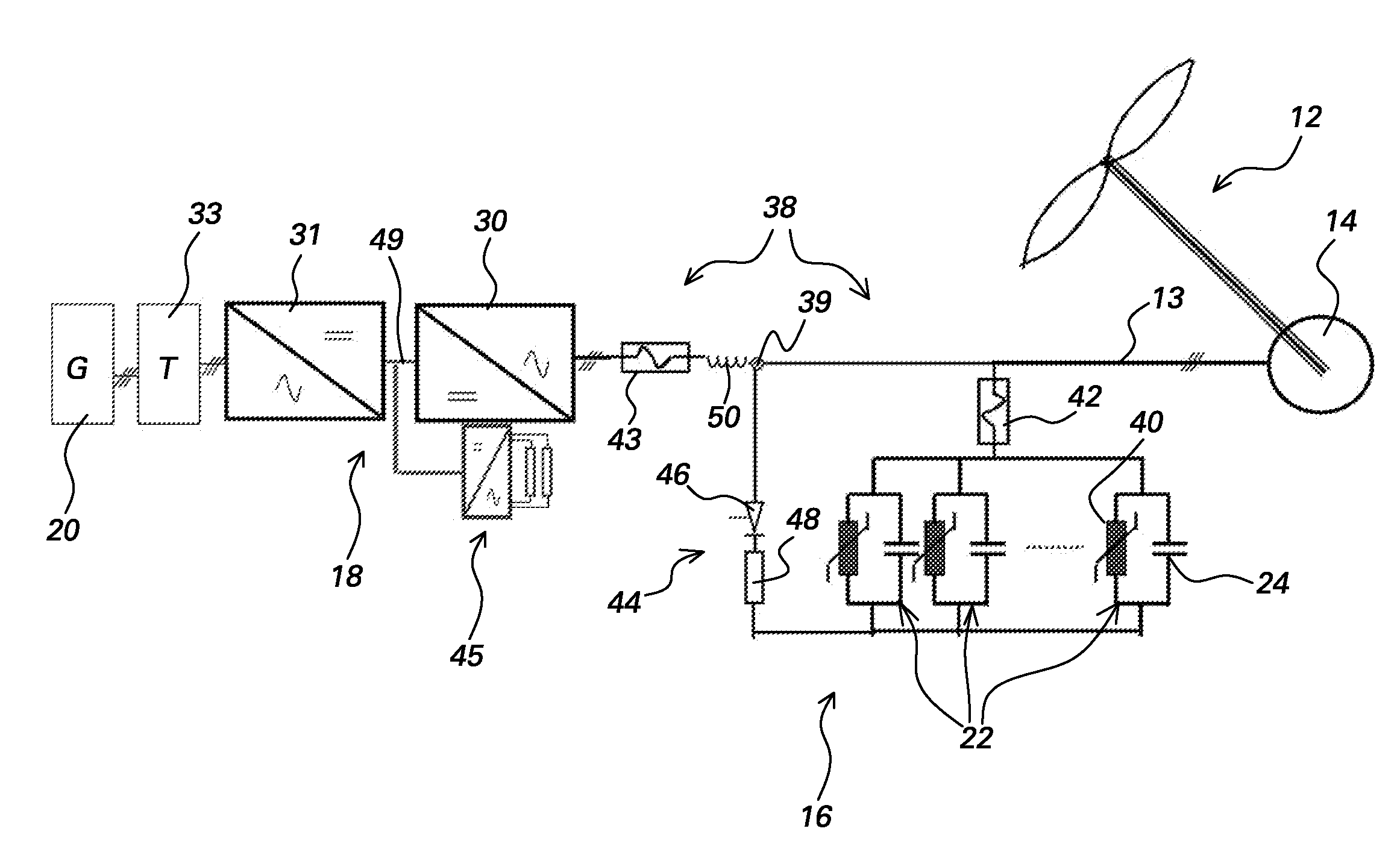
[0020]FIG. 1 is a single line block diagram of a power generation system 10 in accordance with one embodiment disclosed herein. Power system 10 comprises a prime mover 12, an electrical machine 14 coupled to prime mover 12, a reactive power supply assembly 16 coupled to electrical machine 14, and a power electronic converter 18 coupled to the reactive power supply assembly and configured for transferring power from the electrical machine to a grid 20. Electrical machine 14 is configured for converting mechanical power to electrical power in embodiments operating in a generating mode (such as wind or hydro turbine systems, for example) or for converting electrical power to mechanical power in embodiments operating in a motoring mode (such as ship propulsion systems, for example). Electrical machine 14 typically has a power factor of less than or equal to 0.7 and in one embodiment comprises a magnetically geared machine such as described in aforementioned US20070186692. Reactive power...


PUM


Abstract

A power generation system includes: a prime mover; an electrical machine coupled to the prime mover and configured for converting mechanical power to electrical power, the electrical machine having a power factor of less than or equal to 0.7; a reactive power supply assembly coupled to the electrical machine and configured to supply reactive power to the electrical machine; and a power electronic converter coupled to the reactive power supply assembly and configured for transferring power from the electrical machine to a grid.

Description

BACKGROUND[0001]The present disclosure relates generally to electric power generation and more particularly to electric power generation systems including magnetically geared machines.[0002]Electrical machines such as motors and generators typically deliver more power at high speeds than at low speeds. In order to adapt a high-speed, rotating electrical machine to a high-torque, lower speed mechanical component (such as a prime mover in the case of a generator or a load in the case of a motor), mechanical gear boxes are typically selected because the cost of having a high-speed electrical machine coupled with mechanical gearing for speed / torque conversion is lower than the cost of a low-speed electrical machine. Mechanical gearing has some inherent disadvantages with respect to acoustic noise, vibration, reliability, and maintenance, for example.[0003]Magnetic gears do not require physical contact between an input shaft and an output shaft but have traditionally received relatively ...

Claims


Application Information

Patent Timeline
Patent Type & Authority Applications(United States)
IPC IPC(8): H02P9/04F03D9/00H02H7/16
CPCH02P9/14H02P2101/15H02P2101/10Y02E10/725F03D9/255H02J3/1885Y02E10/72Y02E40/30H02K51/00H02J3/1821
Inventor MARI, JORGEWASZAK, MICHAL-WOLFGANGSCHRAMM, SIMON
Owner GENERAL ELECTRIC CO
Why Eureka
Try Eureka