Axial flow fan

Active Publication Date: 2009-03-26
NIDEC CORP
View PDF14 Cites 17 Cited by
  • Summary
  • Abstract
  • Description
  • Claims
  • Application Information

AI Technical Summary

Benefits of technology

[0010]In order to overcome the problems described above, an axial flow fan according to preferred embodiments of the present invention comprises an impeller rotatable about a central axis and including a plurality of blades, a hollow member accommodating therein the impeller, a base portion arranged at the hollow member and supporting the impeller in a rotatable manner, a plurality of inner air guide members each connected to the base member, a plurality of outer air guide members each connected to the hollow member, and a connecting member connecting the inner air guide members and the outer air guide mem

Problems solved by technology

In recent years, various electronic equipments have been becoming smaller and smaller.
However, such devices fail if temperature of their electronic equipments or processor unit

Method used


Image

  • Axial flow fan
  • Axial flow fan
  • Axial flow fan

Examples


Embodiment Construction

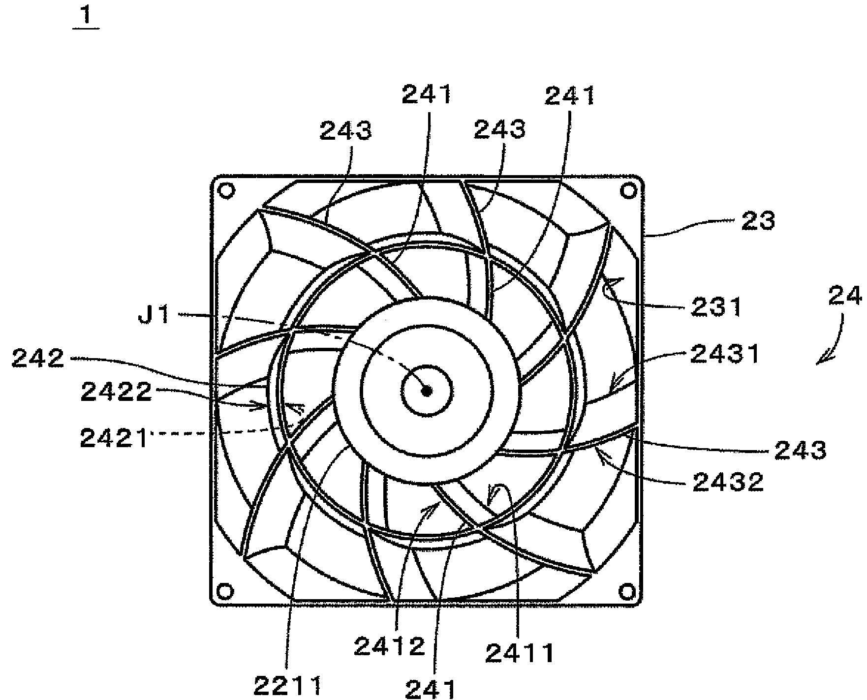
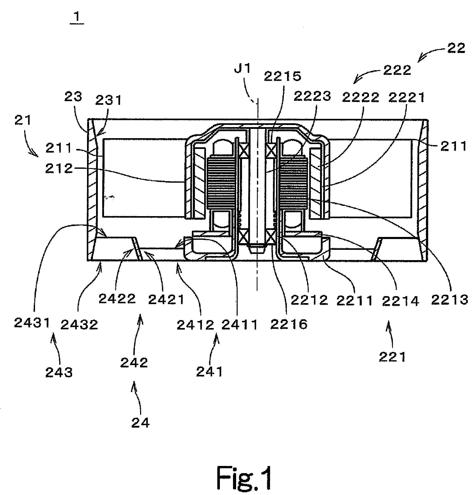
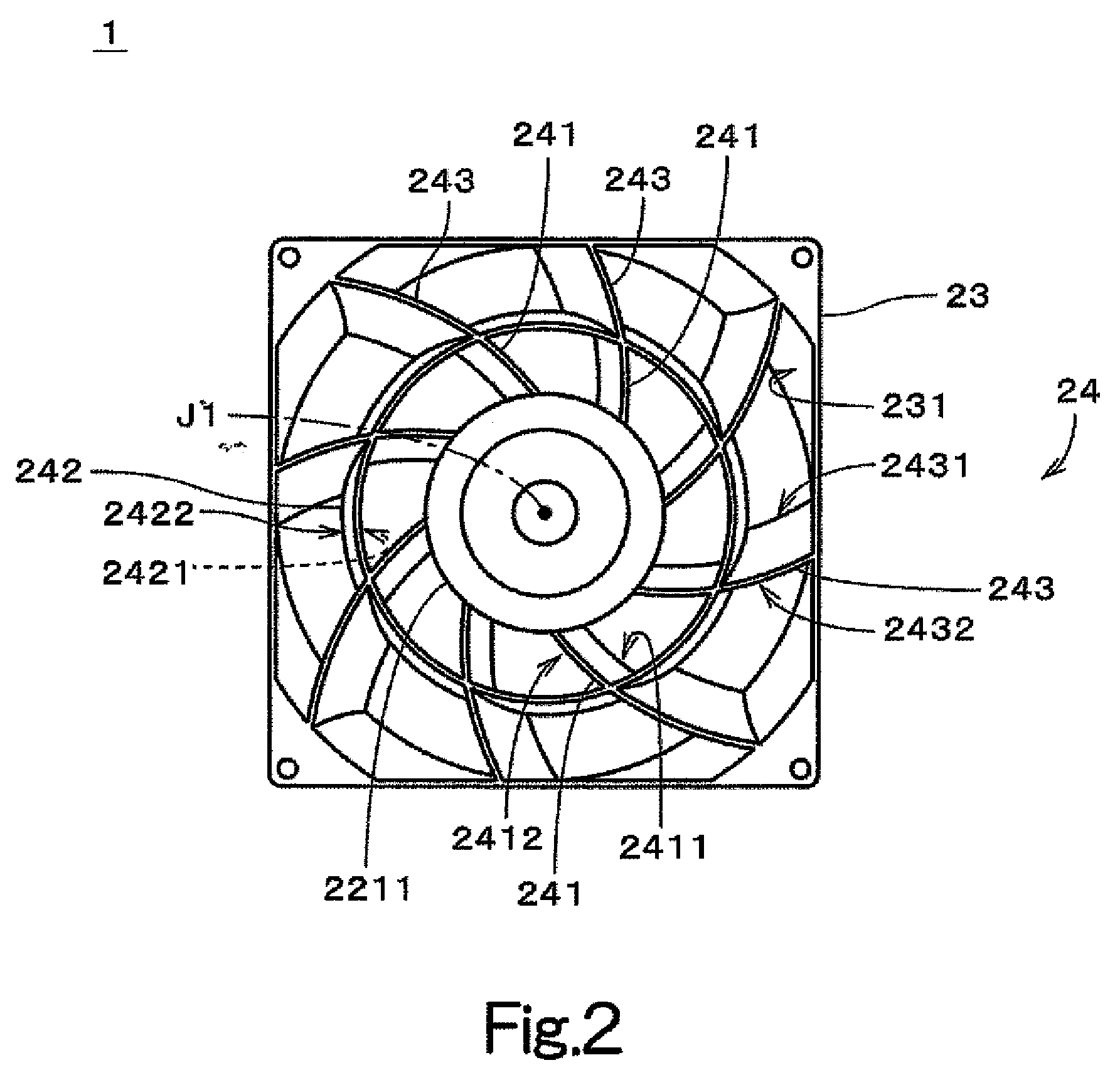
[0027]Note that in the description of preferred embodiments of the present invention herein, words such as upper, lower, left, right, upward, downward, top, and bottom for describing positional relationships between respective members and directions merely indicate positional relationships and directions in the drawings. Such words do not indicate positional relationships and directions of the members mounted in an actual device. Also note that reference numerals, figure numbers, and supplementary descriptions are shown below for assisting the reader in finding corresponding components in the description of the preferred embodiments below to facilitate an understanding of the present invention. It is understood that these expressions in no way restrict the scope of the present invention. Also note that in the description hereafter, an upper side and a lower side of the axial flow fan 1 in accordance with FIG. 1 will be respectively referred to as an “inlet side” and an “outlet side”...


PUM


Abstract

An axial flow fan according to the present invention comprises an impeller which rotates about a central axis and including a plurality of blades, a hollow member accommodating therein the impeller, a base portion which is arranged at the hollow member and supports the base portion in a rotatable manner, a plurality of inner air guide members each connected to the base portion, and a plurality of outer air guide members each connected to the hollow member.
The inner air guide members and the outer air guide members each include a first edge member and a second edge portion. A length of he first edge member and that of the second edge member of the outer air guide member are greater than those of the first edge member and the second edge member of the inner air guide member.

Description

BACKGROUND OF THE INVENTION[0001]1. Field of the Invention[0002]The present invention relates to an axial flow fan.[0003]2. Description of the Related Art[0004]In recent years, various electronic equipments have been becoming smaller and smaller. Also, the amount of heat generated by electronic devices in the electronic equipments has been greater. However, such devices fail if temperature of their electronic equipments or processor units becomes too high. Therefore, a fan which is usually arranged inside an electronic device is typically used to cool the electronic components and processor units of the electronic device.[0005]For example, an axial flow fan is often used to cool the electronic components and processor units of the electronic device. The axial flow fan typically includes a housing which accommodates therein an impeller which rotates centered about the central axis thereof. The impeller typically includes a cup having a substantially cylindrical shape, and a plurality...

Claims


Application Information

Patent Timeline
IPC IPC(8): F04D29/54
CPCF04D29/542F04D25/0613F04D29/544
Inventor TAKESHITA, HIDENOBUFUKUNAGA, TOSHIKAZUTATSUNO, TSUNENORI
Owner NIDEC CORP
Why Eureka
Try Eureka