Real-time arc control in electrosurgical generators

a generator and real-time control technology, applied in the field of real-time arc control in electrosurgical generators, electrosurgical generators, etc., can solve the problems of not configured configurations for detecting and controlling arcing conditions, heat and destruction surrounding issues,

Active Publication Date: 2009-03-26
COLORADO STATE UNIVERSITY +1
View PDF104 Cites 84 Cited by
  • Summary
  • Abstract
  • Description
  • Claims
  • Application Information

AI Technical Summary

Benefits of technology

[0010]According to a further embodiment of the present disclosure, an electrosurgical generator is disclosed. The electrosurgical generator includes a radio frequency output stage configured to generate a radio frequency waveform having a current waveform and a voltage waveform, a sensor circuit configured to measure voltage and current of a radio frequency waveform during a predetermined sampling period, and a controller configured to compare the voltage waveform and the current waveform and to provide a signal representative of the comparison. The controller includes a total charge calculator module configured to temporally integrate current of the radio frequency waveform and in particular the current during the interval when the current waveform departs from the voltage waveform to determine the total charge deposited by the radio frequency waveform during the predetermined sampling period as well as during the arc events. The controller also includes a total energy calculator module configured to integrate total power deposited by the radio frequency waveform to determine the total energy deposited by the radio frequency waveform during the predetermined sampling period for the radio frequency waveform and for arc events. The controller is further configured to determine an arc event as a function of the total charge and total energy and to adjust the output of the electrosurgical generator if the arc event is determined to avoid undesired tissue damage by setting a threshold energy above which the arc event is extinguished.

Problems solved by technology

Typically, the current density is very high near the tip of the needle electrode, which tends to heat and destroy surrounding issue.
These configurations are not configured for detecting and controlling arcing conditions between the active electrode and tissue.

Method used


Image

  • Real-time arc control in electrosurgical generators
  • Real-time arc control in electrosurgical generators
  • Real-time arc control in electrosurgical generators

Examples


Embodiment Construction

[0015]Particular embodiments of the present disclosure are described hereinbelow with reference to the accompanying drawings. In the following description, well-known functions or constructions are not described in detail to avoid obscuring the present disclosure in unnecessary detail.

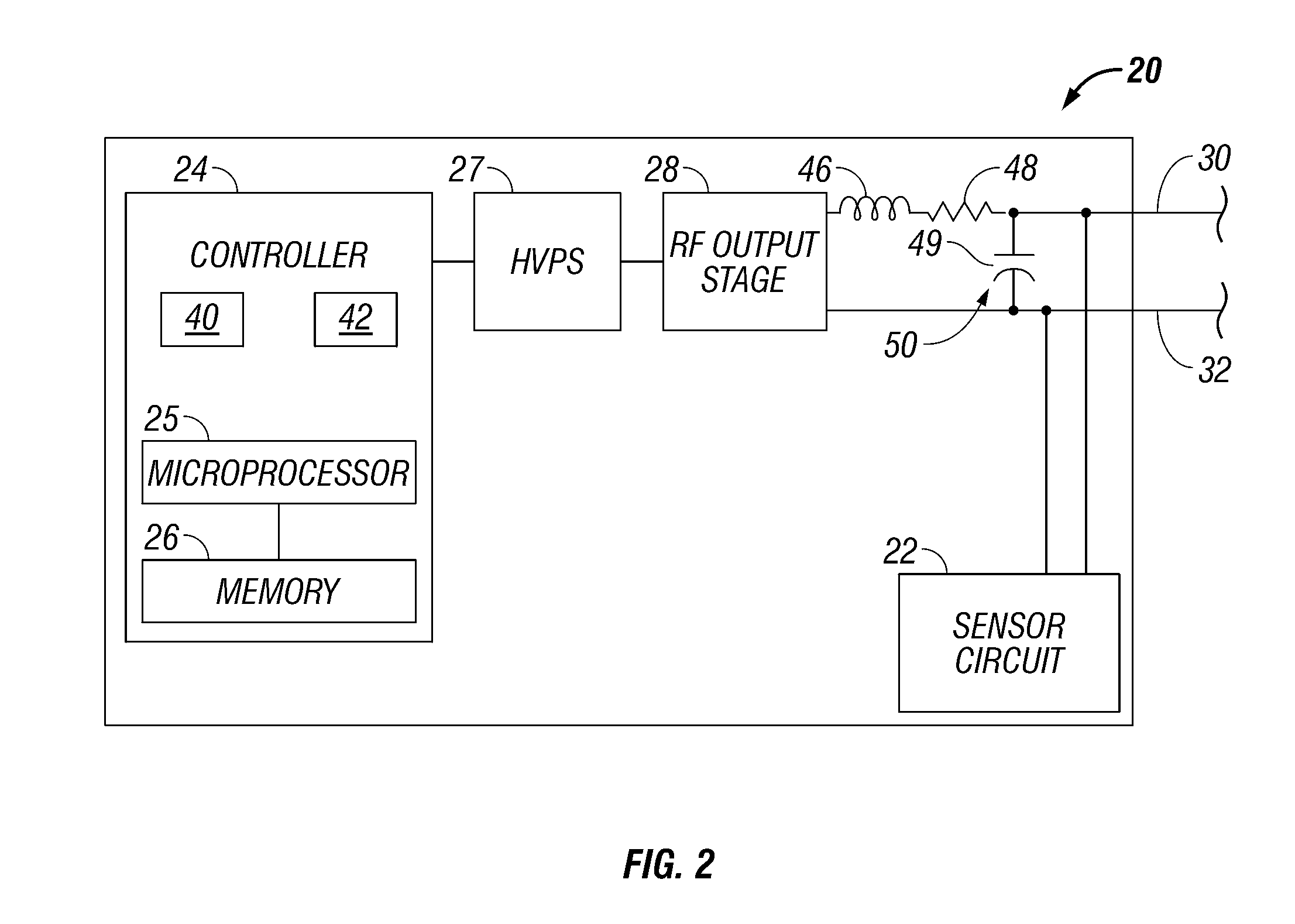
[0016]The generator according to the present disclosure can perform monopolar and bipolar electrosurgical procedures, including vessel sealing procedures. The generator may include a plurality of outputs for interfacing with various electrosurgical instruments (e.g., a monopolar active electrode, return electrode, bipolar electrosurgical forceps, footswitch, etc.). Further, the generator includes electronic circuitry configured for generating radio frequency power specifically suited for various electrosurgical modes (e.g., cutting, blending, division, etc.) and procedures (e.g., monopolar, bipolar, vessel sealing).

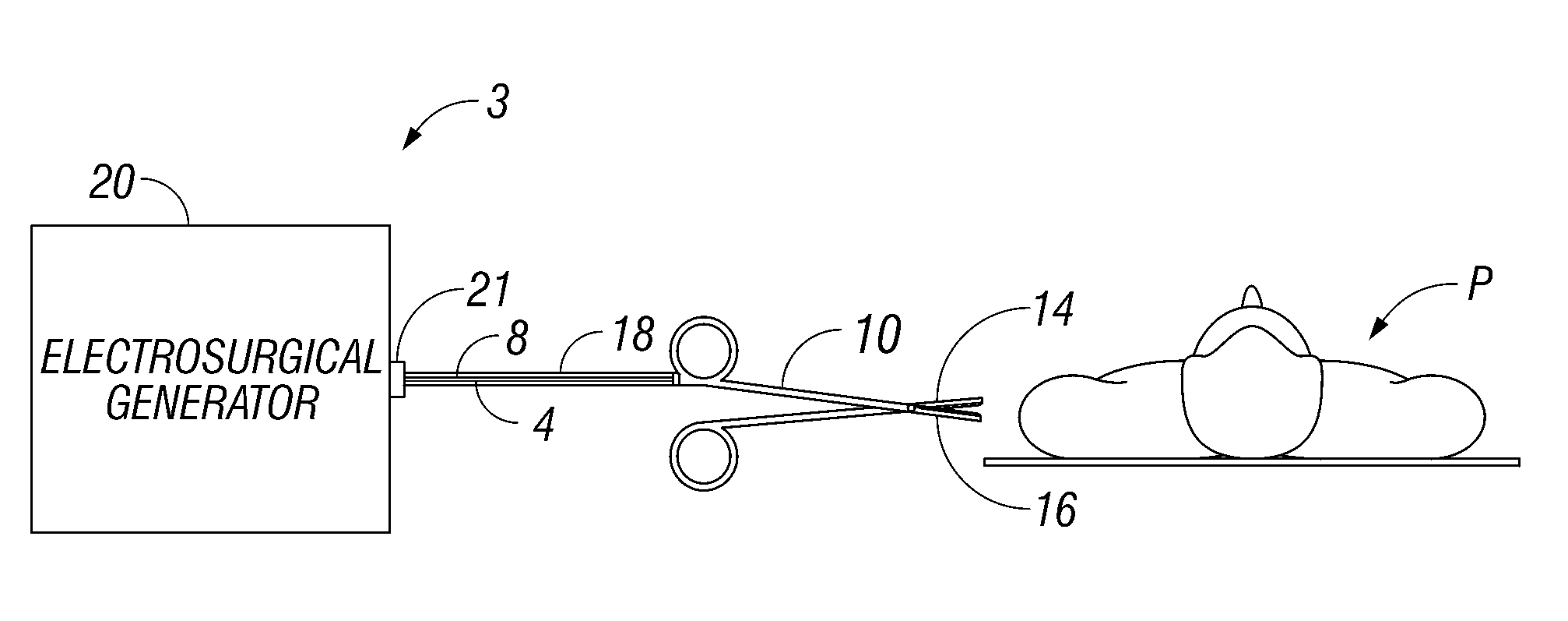
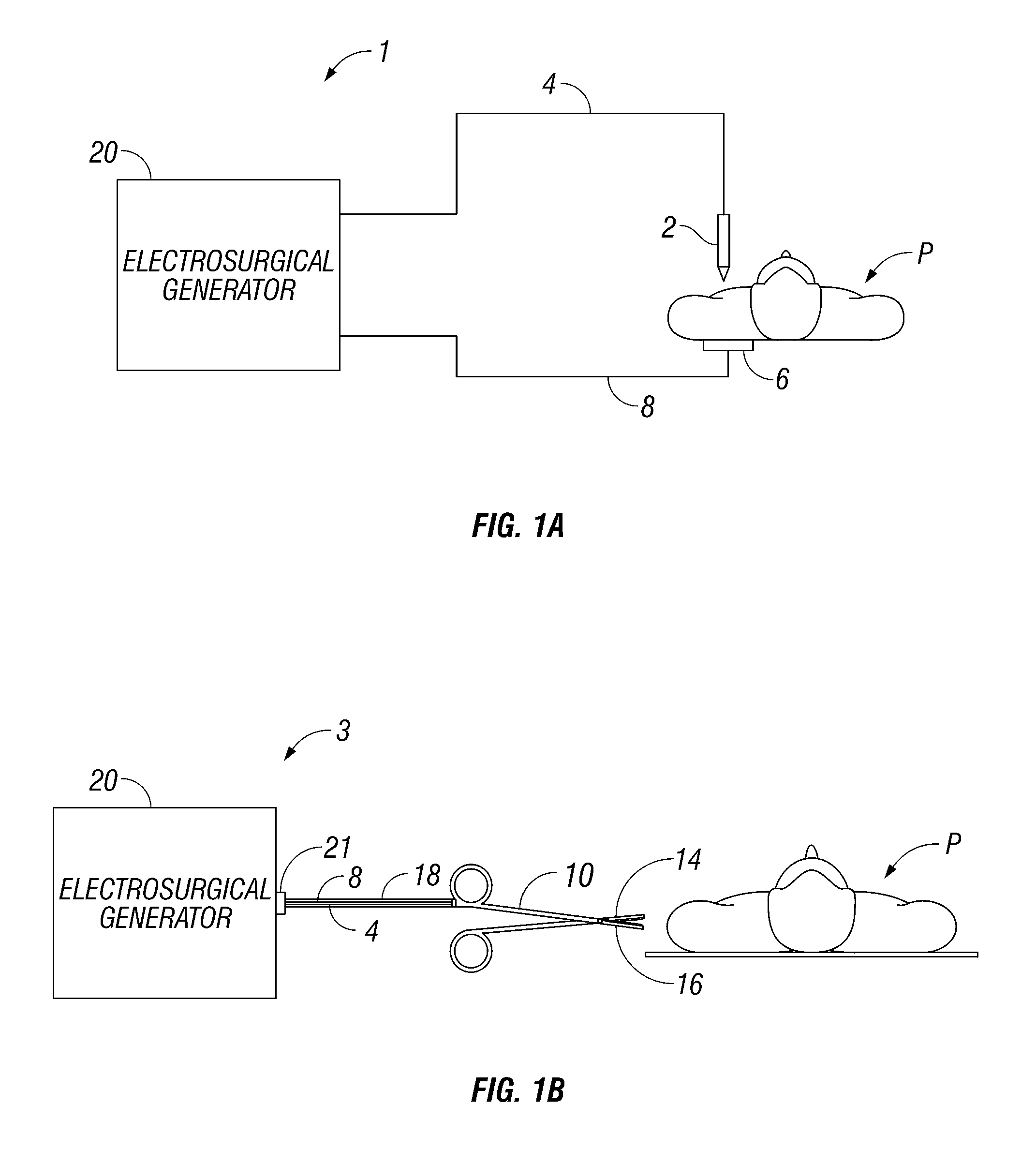
[0017]FIG. 1A is a schematic illustration of a monopolar electrosurgical system 1 accord...


PUM


Abstract

An electrosurgical generator is disclosed. The generator includes a radio frequency output stage configured to generate a radio frequency waveform and a sensor circuit configured to measure a property of the radio frequency waveform during a predetermined sampling period to determine whether an arc event has occurred. The generator also includes a controller configured to determine a total charge and/or total energy deposited by the radio frequency waveform during the predetermined sampling period associated with the arc event. The controller is further configured to adjust the output of the electrosurgical generator based on at least one parameter to limit arcing.

Description

BACKGROUND[0001]1. Technical Field[0002]The present disclosure relates to electrosurgical apparatuses, systems and methods. More particularly, the present disclosure is directed to electrosurgical generators configured to control energy output on a per arc basis. The generator detects aberrations within continuous or pulsed waveforms indicative of sudden changes in the current. In particular the generator monitors for deviations from the sinusoidal or pulsed sinusoidal current waveforms as compared to the voltage waveform.[0003]2. Background of Related Art[0004]Energy-based tissue treatment is well known in the art. Various types of energy (e.g., electrical, ultrasonic, microwave, cryogenic, heat, laser, etc.) are applied to tissue to achieve a desired result. Electrosurgery involves application of high radio frequency electrical current to a surgical site to cut, ablate, coagulate or seal tissue. In monopolar electrosurgery, an active electrode delivers radio frequency energy from ...

Claims


Application Information

Patent Timeline
Patent Type & Authority Applications(United States)
IPC IPC(8): A61B18/18
CPCA61B18/1206A61B18/1445A61B2018/00648A61B18/18A61B2018/00702A61B2018/00779A61B2018/00875A61B2018/0066
Inventor COLLINS, GEORGE J.MOORE, CAMERON A.WARD, ARLEN K.
Owner COLORADO STATE UNIVERSITY
Why Eureka
Try Eureka