Transpedicular, extrapedicular and transcorporeal partial disc replacement

a technology of partial disc replacement and transpedicular disc, which is applied in the field of disc arthroplasty or partial disc replacement, can solve the problems of significant trauma of lumbar disc replacement, instability of devices in the disc space, and approach associated with serious complications, so as to avoid the pitfalls of partial disc replacement, avoid severe surgical trauma, and avoid further injury to the annulus

Active Publication Date: 2009-03-26
SPINAL ELEMENTS INC
View PDF12 Cites 26 Cited by
  • Summary
  • Abstract
  • Description
  • Claims
  • Application Information

AI Technical Summary

Benefits of technology

[0006]The described embodiments endeavor to avoid the severe surgical trauma of the current partial disc arthroplasty by using minimally invasive techniques and also to avoid the pitfalls of partial disc replacements by avoiding further injury to the annulus and by utilizing intraosseous anchoring mechanisms to stabilize the device, instead of depending on a compromised annulus. The device and method avoid accessing the disc space through the disc wall and rather are designed to be inserted through one or both of the vertebral pedicle or vertebral body. The device and method utilize minimally invasive techniques for partial disc arthroplasty.

Problems solved by technology

The surgical trauma for the lumbar disc replacement is significant, and the approach has been associated with serious complications.
The current minimally invasive partial disc replacement devices are at experimental stages in the USA, and most have significant design flaws, notably instability of the devices in the disc spaces, and reliance on the already compromised annulus fibrosus to contain the devices.
Furthermore, implantation of the current devices requires further violation of the annulus to implant the devices.

Method used


Image

  • Transpedicular, extrapedicular and transcorporeal partial disc replacement
  • Transpedicular, extrapedicular and transcorporeal partial disc replacement
  • Transpedicular, extrapedicular and transcorporeal partial disc replacement

Examples


Embodiment Construction

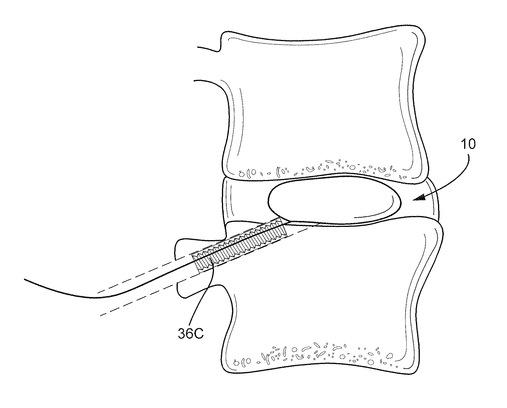
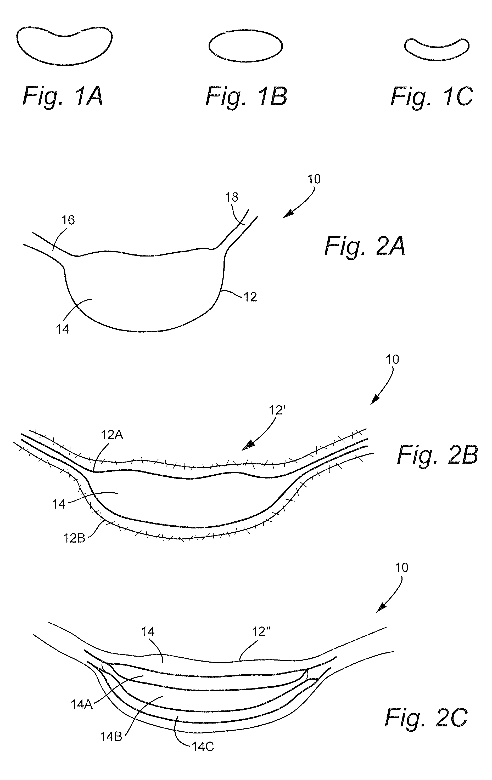
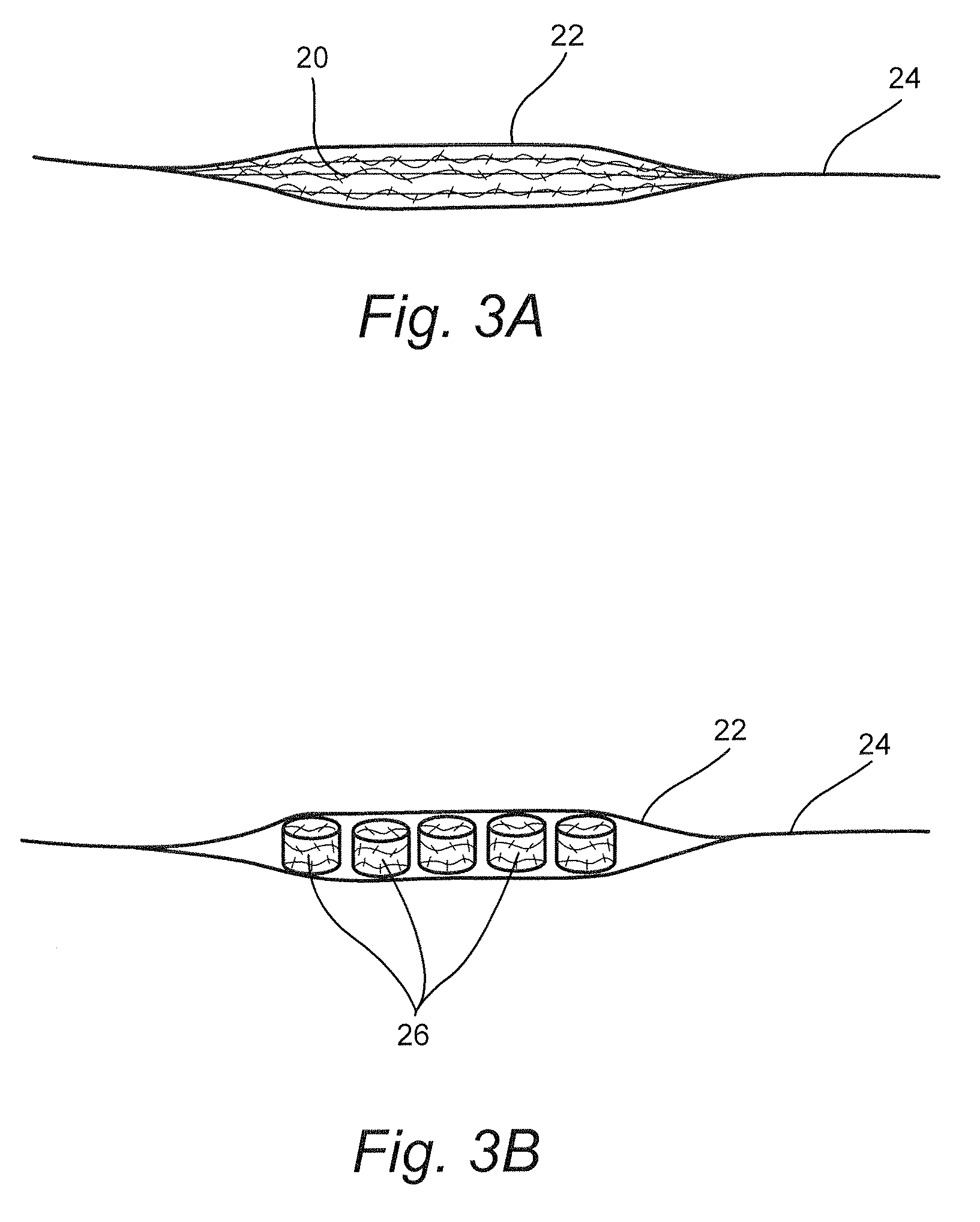
[0019]With reference to FIGS. 1A-1C and FIGS. 2A-2C, a nucleus replacement 10 mimics a native annulus in shape and function for use in partial disc arthroplasty. As shown in FIGS. 1A-1C, the replacement 10 can take numerous shapes including, without limitation, bean shaped, oval shaped, cylindrical shaped (or more accurately banana-shaped), and the like. The replacement 10 generally includes a jacket 12 that includes a compartment 14 and first and second anchoring limbs 16, 18. As described in more detail below, the anchoring limbs 16, 18 facilitate positioning of the jacket 12 in the disc space and enable the jacket 12 to be secured in the disc space. In FIG. 2A, the jacket 12 includes a single compartment 14. The jacket 12 may be formed of numerous suitable materials, including, without limitation, elastic or inelastic fabric, which may be pervious or impervious. FIG. 2B shows an embodiment utilizing a double jacket 12′ including an inner jacket 12A and an outer jacket 12B. The ou...


PUM

PropertyMeasurementUnit
shapeaaaaaaaaaa
stiffnessaaaaaaaaaa
forcesaaaaaaaaaa

Abstract

A nucleus replacement mimics a native annulus in shape and function for use in partial disc arthroplasty. The nucleus replacement includes a jacket having a compartment, a first anchoring limb on one side of the compartment, and a second anchoring limb on an opposite side of the compartment. The jacket is insertable into a disc space through an operating channel in at least one of the vertebral pedicle and the vertebral body. A shock absorbing material is injectable into the compartment after installing the jacket into the disc space. The shock absorbing material has characteristics that absorb loads on the replacement.

Description

CROSS-REFERENCES TO RELATED APPLICATIONS[0001]This application claims the benefit of U.S. Provisional Patent Application Ser. No. 60 / 973,899, filed Sep. 20, 2007, the entire content of which is herein incorporated by reference.STATEMENT REGARDING FEDERALLY SPONSORED RESEARCH OR DEVELOPMENT[0002](NOT APPLICABLE)BACKGROUND OF THE INVENTION[0003]The invention relates to disc arthroplasty (or partial disc replacement) and, more particularly, to a nucleus replacement that mimics a native annulus in shape and function for use in partial disc arthroplasty.[0004]The gold standard for the lumbar and cervical disc degeneration is currently fusion of the diseased motion-segment. The outcomes of the various fusion techniques have generally been satisfactory. Elimination of motion at a joint naturally produces stiffness and this in turn leads to transfer of forces normally absorbed by the motion-segments to the adjacent joints. As a result of the increased forces to which the adjoining joints ar...

Claims


Application Information

Patent Timeline
Patent Type & Authority Applications(United States)
IPC IPC(8): A61F2/44
CPCA61B17/0401A61F2/441A61F2002/30075A61F2002/30462A61F2002/305A61F2002/30583A61F2220/0075A61F2002/30884A61F2002/444A61F2002/4677A61F2210/0061A61F2210/0085A61F2220/0025A61F2002/30586
Inventor OSMAN, SAID G.
Owner SPINAL ELEMENTS INC
Why Eureka
Try Eureka